Lock with a sliding block movably received in the control knob to selectively drive the latch

Inactive Publication Date: 2005-03-22
JIN TAY IND CO LTD
View PDF13 Cites 20 Cited by
  • Summary
  • Abstract
  • Description
  • Claims
  • Application Information

AI Technical Summary

Benefits of technology

Another objective of the present invention is to provide first stop on an outer periphery of the sliding seat and a second stop on an inner periphery of the casing to

Problems solved by technology

Therefore, a key to the lock is unnecessary

Method used


Image

  • Lock with a sliding block movably received in the control knob to selectively drive the latch
  • Lock with a sliding block movably received in the control knob to selectively drive the latch
  • Lock with a sliding block movably received in the control knob to selectively drive the latch

Examples


Example

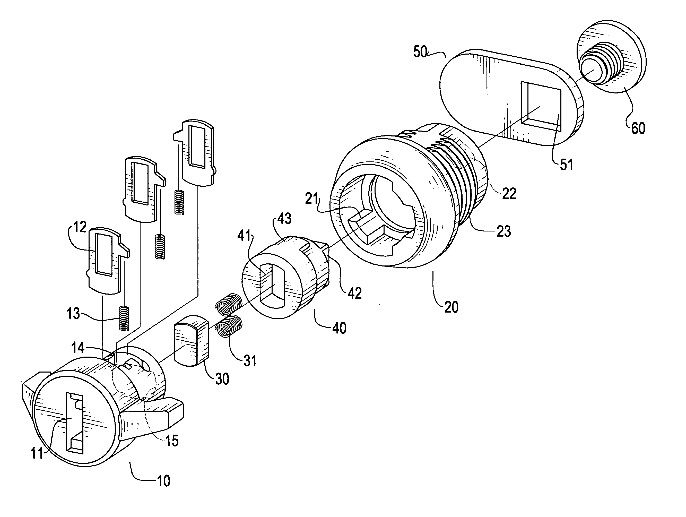
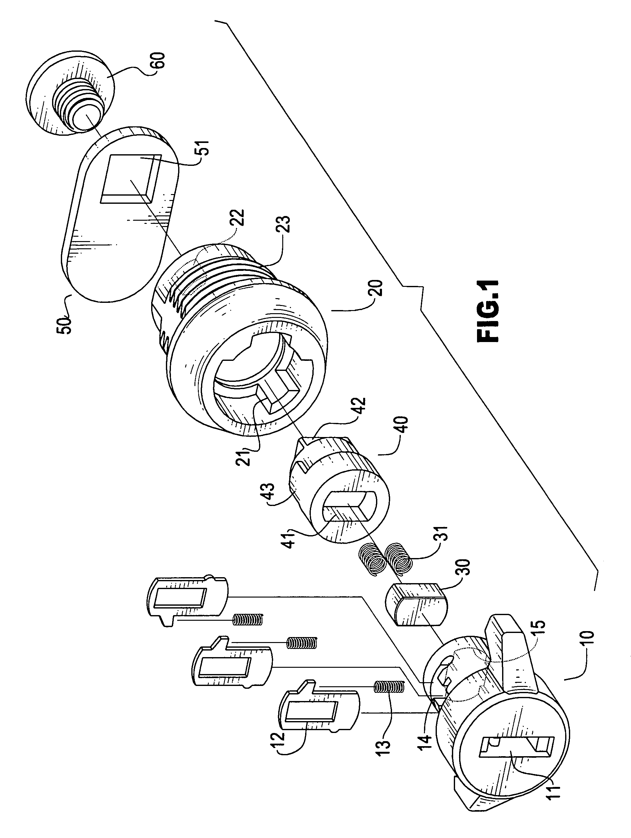
With reference to FIG. 1, the lock in accordance with the present invention has a control knob (10), a sliding block (30), a sliding seat (40), a casing (20), a latch (50) and a plug (60).

The control knob (10) has a keyway (11) centrally defined in the control knob (10) to allow an extension of a key (not shown), multiple locking slits (14) defined through a periphery of the control knob (10) to respectively receive therein a locking plate (12) and a spring (13) and a receiving space (15) defined in a free end face of the control knob (10) to communicate with the keyway (11). However, the principle of the movement of the locking plates (12) and the springs (13) which are received in the corresponding locking slits (14) is well known in the art so that detailed description of how the locking plates (12) are moved according to different situation is thus omitted herein.

The sliding block (30) is a cube, preferably, a hexahedron. At least one expansion spring (31) (two are shown in th...


PUM


Abstract

A lock includes a control knob with a keyway and a receiving space defined in a distal end face of the control knob to correspond to the receiving hole of the sliding seat. The sliding block is able to selectively be received at a joint of the control knob and the sliding block to allow movement of the control knob to drive the latch to move accordingly.

Description

BACKGROUND OF THE INVENTION 1. Field of the Invention The present invention relates to a lock, and more particularly to a lock with a sliding block movably received in the control knob such that the pivotal movement of the control knob is able to drive the latch to move accordingly. 2. Description of Related Art When referring to a lock with a pivotal control knob and a latch driven by the pivotal movement of the control knob, normally, the latch is firmly mounted on the control knob so that when the control knob is pivoted, the latch is driven to rotate in a direction the same as that of the control knob. When the latch is rotated, the latch is able to connect / disconnect to a locking bar which is firmly mounted on a surface to switch between a locking / unlocking status. In general, a wide variety of different elements may be involved to firmly mount the latch on the control knob, which complicates the structure of the lock and hence the manufacture cost is high. Furthermore, the use...

Claims


Application Information

Patent Timeline
IPC IPC(8): E05B17/00E05B29/00E05B17/04E05B13/00E05B13/10E05B9/06
CPCE05B29/00E05B17/04E05B13/108Y10T70/5823Y10T70/7599Y10T70/7638Y10T70/7706
Inventor MIAO, TONY
Owner JIN TAY IND CO LTD
Why Eureka
Try Eureka