Water rescue device

A hull and connecting plate technology, which is applied to lifesaving in water, transportation and packaging, ship construction, etc., can solve the problems of limited load capacity and limited application scope, and achieve the effect of increasing rescue load, not easy to overturn, and high safety factor.

Active Publication Date: 2021-12-31
HUAIYIN INSTITUTE OF TECHNOLOGY
View PDF16 Cites 1 Cited by
  • Summary
  • Abstract
  • Description
  • Claims
  • Application Information

AI Technical Summary

Problems solved by technology

Although the rescue ship of this application has improved the stability of the hull, its scope of application is limited and its load capacity is limited

Method used


Image

  • Water rescue device
  • Water rescue device
  • Water rescue device

Examples


Embodiment 1

[0057] The water rescue device of the present embodiment includes:

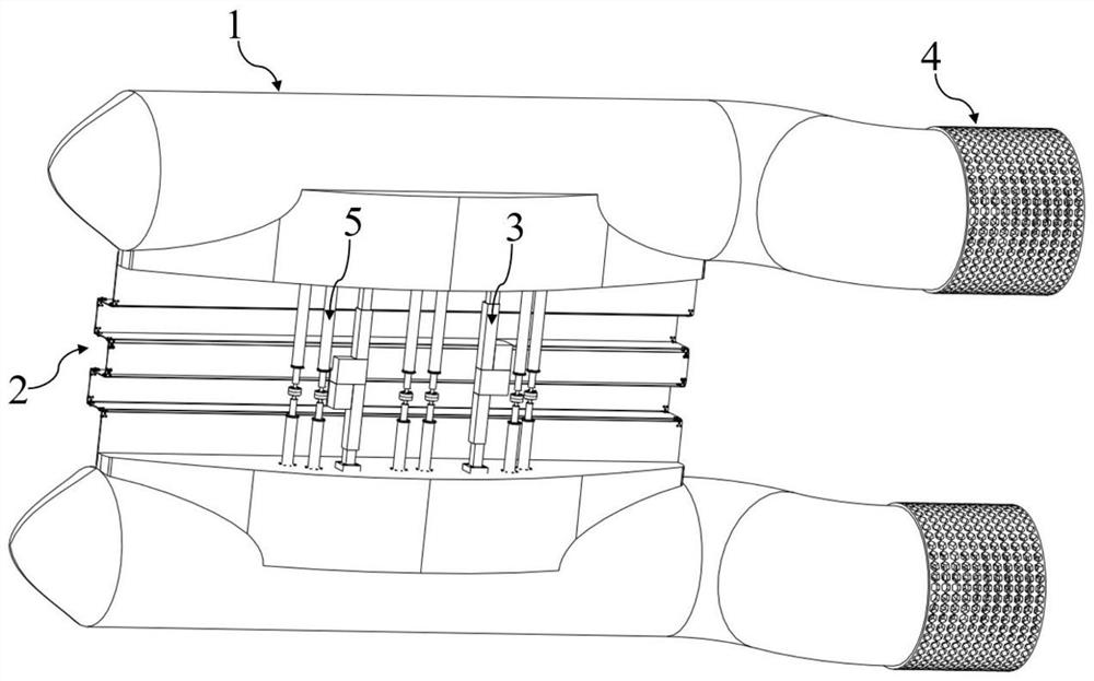
[0058] There are two hulls 1, arranged parallel to each other and side by side, with a space between the two hulls 1;

[0059] The connecting plate 2 is placed between the two hulls 1 to connect the two hulls 1, and the connecting plate 2 is scalable;

[0060] The telescopic drive unit 3 is placed between the two hulls 1 to connect the two hulls 1, and the telescopic drive unit 3 drives the two hulls 1 to approach or move away;

[0061] There are two stern drive units 4, which are respectively arranged at the tail of each hull 1, and the stern drive unit 4 drives the hull 1 to travel.

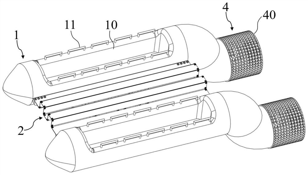
[0062] Such as figure 1 and figure 2 As shown, the water rescue device of the present embodiment comprises two hulls 1, and the top of each hull 1 is provided with a cabin 10 from top to bottom, and a handrail 11 is formed on the top edge of the cabin 10, and a telescopic connecting plate 2 connects the two hulls 1. Conne...

Embodiment 2

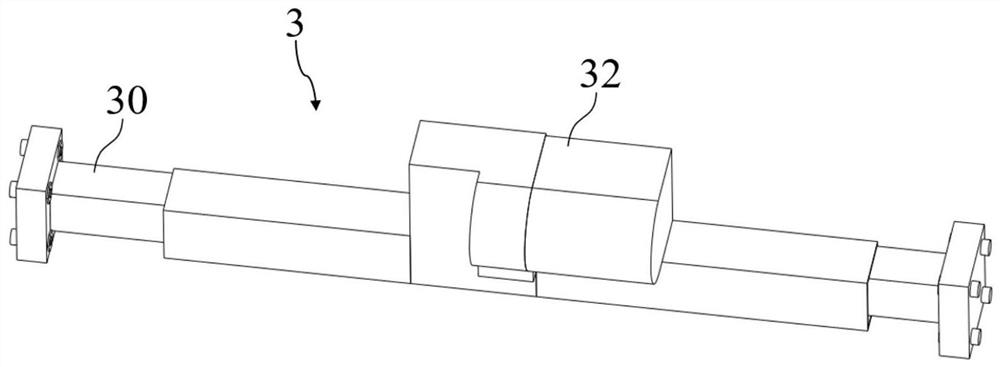
[0066] The water rescue device of this embodiment is further improved on the basis of Embodiment 1, and the telescopic drive unit 3 includes:

[0067] There are two telescopic sleeve rods 30, which are arranged symmetrically with each other. One end of the telescopic sleeve rod 30 is fixedly connected to the inner surface of the hull 1. threaded hole 300;

[0068] Screw rod 31, which is placed between two telescopic sleeve rods 30, the two ends of the screw rod 31 are respectively screwed with the threaded holes 300 of each telescopic sleeve rod 30;

[0069] Cover body 32, which is set on the outside of screw rod 31 and telescopic sleeve rod 30;

[0070] A driver 33, which is fixedly connected in the cover body 32, provides a driving force;

[0071] The gear transmission assembly 34 is placed in the cover body 32 and drives the driving member 33 to the screw rod 31 .

[0072] Such as image 3 and Figure 5 As shown, in this embodiment, the shape of the telescopic sleeve r...

Embodiment 3

[0075] The water rescue device of this embodiment is further improved on the basis of Embodiment 2, and the telescopic drive unit 3 also includes:

[0076] There are two limiting members 35 , which are respectively sleeved on the screw rods 31 on both sides of the gear transmission assembly 34 .

[0077] Such as Figure 4 and Figure 5 As shown, the limiting member 35 of this embodiment is a nut, and the two nuts are respectively fixedly sleeved on the screw rods 31 on both sides of the gear three 342. The side faces of the nut interfere with the end faces of the telescopic sleeve rods 30. When the 30 is close to the nut, it will interfere with the nut and stop, thereby effectively preventing the two telescopic sleeve rods 30 from being too close to damage the gear transmission assembly 34 and affecting the subsequent normal operation of the drive unit.


PUM


Abstract

The invention discloses a water rescue device, and belongs to the field of rescue equipment. The device comprises two ship bodies which are parallel to each other and are arranged side by side, wherein a gap is reserved between the two ship bodies; a connecting plate is arranged between the two ship bodies and connects the two ship bodies, wherein the connecting plate is telescopic; a telescopic driving unit arranged between the two ship bodies, connects the two ship bodies, wherein drives the two ship bodies to be close to or away from each other; and two stern driving units arranged at the tails of the ship bodies correspondingly, wherein the ship bodies are driven by the stern driving units to travel. In the rescue process, when a narrow river channel is encountered, the distance between the two ship bodies is reduced by controlling the telescopic driving unit, the ship bodies can directly pass through the narrow channel, when strong storm waves are encountered or the loading capacity requirement is large, the distance between the two ship bodies is increased by controlling the telescopic driving unit, the connecting plates are unfolded, impact force can be buffered, and the ship bodies are kept balanced; and rescue workers can sit on the connecting plate, and more materials can be placed on the connecting plate, so that the rescue efficiency is improved.

Description

technical field [0001] The invention belongs to the technical field of rescue equipment, and more specifically relates to a water rescue device. Background technique [0002] There are many rivers in our country, the landforms of the basin are complex, the vegetation on both sides is less, the dams are easy to be washed away, and sometimes the bad weather causes floods. [0003] The existing rescue boats have low load capacity and low balance, and are easy to be overturned. Their power system is easily entangled by underwater debris when sailing underwater, which seriously affects the speed of the hull over time, and When facing smaller channels, it is necessary to take a detour, which reduces the efficiency of rescue. [0004] After retrieval, Chinese Patent Publication No.: CN 107651124 A; Publication Date: February 2, 2018; discloses a water rescue ship, comprising: a hatch cover covering the entire hull is provided on the hull, and a middle part of one side of the hatch...

Claims


Application Information

Patent Timeline
Patent Type & Authority Applications(China)
IPC IPC(8): B63C9/02B63B1/14B63B7/00B63H5/16
CPCB63C9/02B63B1/14B63B7/00B63H5/165B63B2007/003
Inventor 徐国慧董育伟万佳杰王溪王潇涵袁烨磊
Owner HUAIYIN INSTITUTE OF TECHNOLOGY
Why Eureka
Try Eureka