Lifting-based variable pitch bearing trepanning equipment beneficial to drilling

A technology of variable pitch bearing and lift type, which is applied in the direction of drilling/drilling equipment, boring/drilling, metal processing equipment, etc., and can solve problems such as easy to walk into the air, affect processing work, and deteriorate the environment of the production workshop , to achieve the effect of improving the collection effect and avoiding excessive movement

Pending Publication Date: 2022-07-05
江阴市恒润传动科技有限公司
View PDF0 Cites 0 Cited by
  • Summary
  • Abstract
  • Description
  • Claims
  • Application Information

AI Technical Summary

Problems solved by technology

[0003] Pitch bearings need to be processed many times before they are put into use. Drilling holes for pitch bearings is one of the essential processes. Most of the existing drilling equipment for pitch bearings uses motors to drive drills to drill holes. A large amount of dust and debris will be generated during the process. If these dust and debris are not cleaned in time, they will easily spread into the air, resulting in a poor environment in the production workshop. At the same time, the dust and debris will cover the top of the pitch bearing, making it impossible for operators to observe The position of the hole will affect the normal processing work

Method used


Image

  • Lifting-based variable pitch bearing trepanning equipment beneficial to drilling
  • Lifting-based variable pitch bearing trepanning equipment beneficial to drilling
  • Lifting-based variable pitch bearing trepanning equipment beneficial to drilling

Examples


Embodiment 1

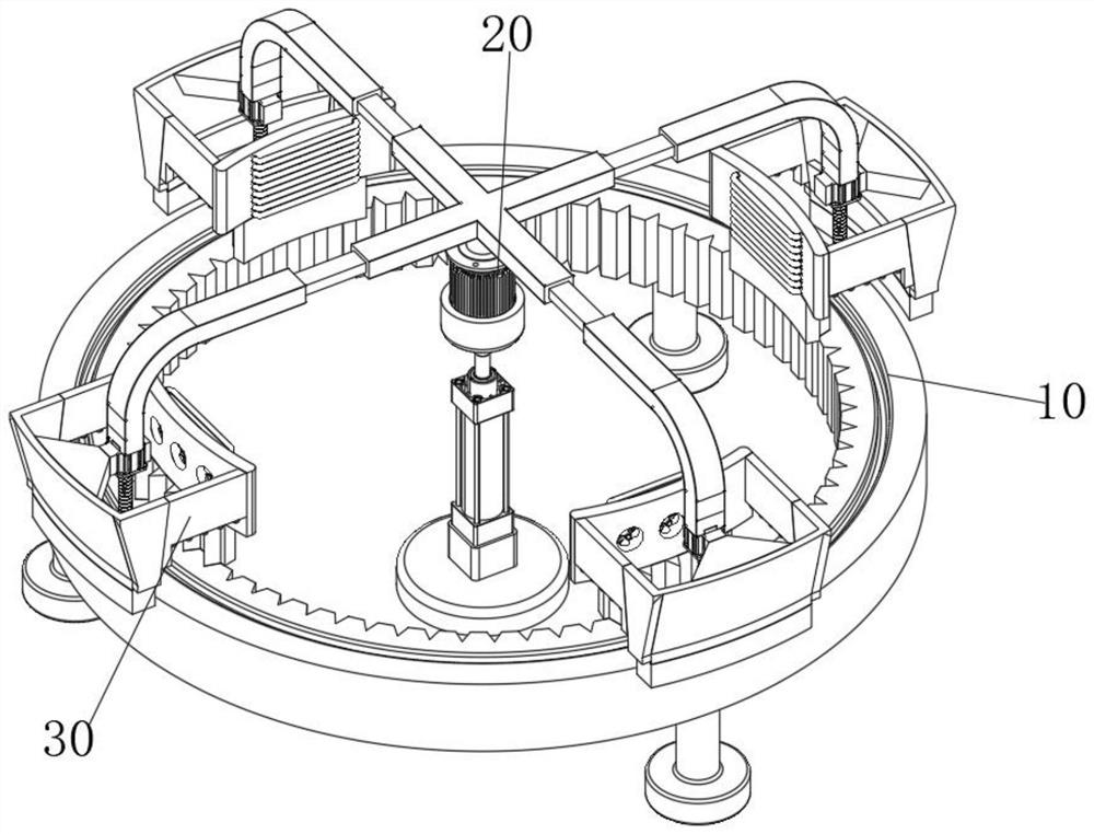
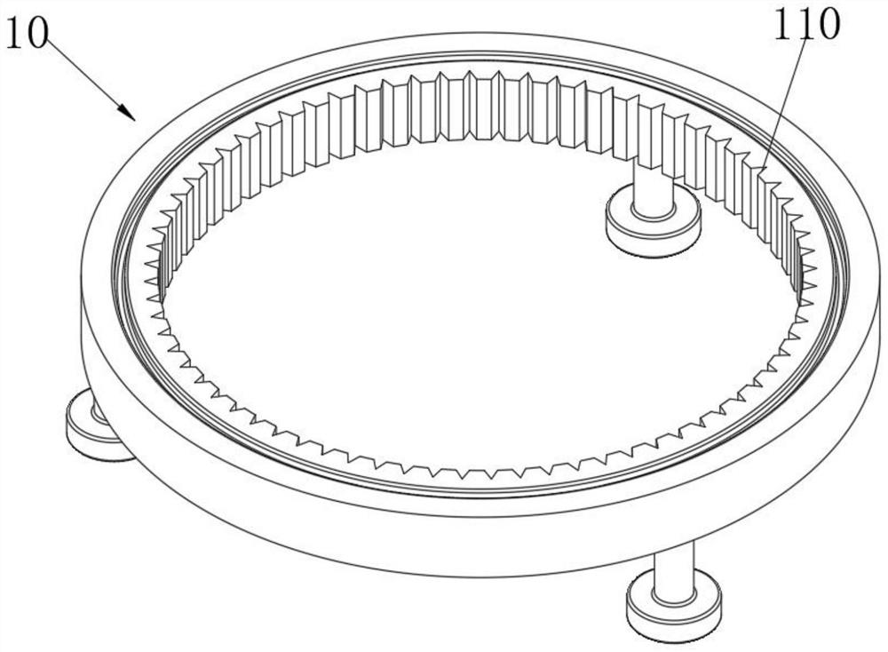
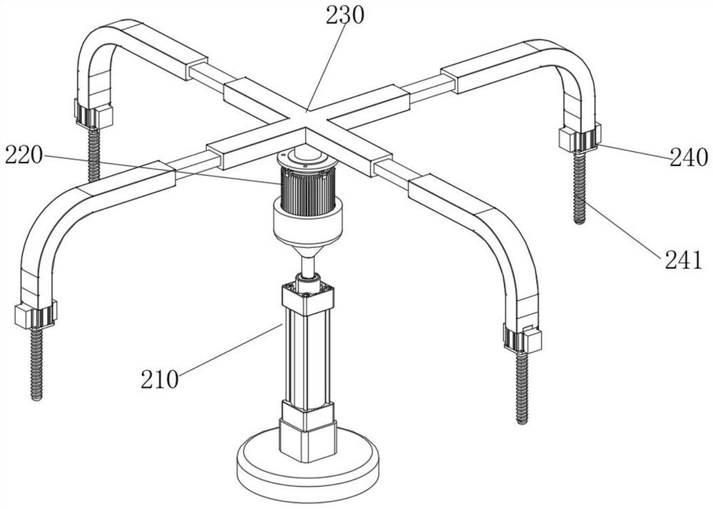
[0040] see Figure 1-Figure 10 As shown in the figure, a pitch bearing drilling device based on a lifting type that facilitates drilling is provided, including a pitch bearing body 10, a connecting assembly 20 arranged at the top of the pitch bearing body 10, and several shielding assemblies installed at the bottom end of the connecting assembly 20. 30. The connecting assembly 20 includes a lifting hydraulic rod 210. The top of the lifting hydraulic rod 210 is provided with a servo motor 220. The top of the servo motor 220 is coaxially connected to a support frame 230. Each side of the support frame 230 is provided with L-shaped rods 231. The L-shaped rods The bottom end of 231 is provided with a drilling motor 240, and the bottom end of the drilling motor 240 is coaxially connected with a drill bit 241. The shielding assembly 30 at least includes:

[0041] The inner veneer 310, the inner veneer 310 has an arc-shaped structure, one side of the inner veneer 310 is attached to t...


PUM


Abstract

The invention relates to the technical field of variable pitch bearing trepanning, in particular to variable pitch bearing trepanning equipment facilitating drilling based on a lifting type. The variable-pitch bearing comprises a variable-pitch bearing body, a connecting assembly arranged at the top end of the variable-pitch bearing body and a plurality of shielding assemblies installed at the bottom end of the connecting assembly, each shielding assembly comprises an inner flitch plate, a plurality of air grooves are formed in the side face of each inner flitch plate, blades are arranged at the inner ends of the air grooves, an outer flitch plate is connected to the side face of each inner flitch plate, and a forward inclined plate is arranged on the side face of each outer flitch plate. And a collecting cavity is formed between the front inclined plate and the inner flitch plate. According to the variable-pitch bearing drilling device, in the process that the variable-pitch bearing body is drilled through the connecting assembly, the inner flitch plate is located on the inner side of the variable-pitch bearing body, the outer flitch plate is located on the outer side of the variable-pitch bearing body, dust and chippings generated in the drilling process are blown by the blade fan, the dust and chippings are blown to the inner end of the collecting cavity, and dust and chippings cleaning and collecting work is completed; and the situation that the punching position of the variable pitch bearing body is covered by generated dust and chippings, and normal punching work is affected is avoided.

Description

technical field [0001] The present invention relates to the technical field of pitch bearing opening, in particular to a pitch bearing opening device based on a lift type that is beneficial for drilling. Background technique [0002] Pitch bearings, also known as blade bearings, are a component of modern wind turbines that connect the rotor hub and rotor blades. The bearings allow the required oscillations to control the load and power of the wind turbine. The pitch system works by adjusting the aerodynamic angle of attack To bring the blades to the desired position, the pitch system is also used for emergency interruption of the turbine system. [0003] Before the pitch bearing is put into use, it needs to be processed many times. Drilling the pitch bearing is one of the essential processes. Most of the existing pitch bearing drilling equipment uses a motor to drive a drill bit for drilling and drilling. A large amount of dust and debris will be generated during the proces...

Claims


Application Information

Patent Timeline
IPC IPC(8): B23B39/20B23B47/22B23Q11/00B23Q11/08
CPCB23B39/20B23Q5/26B23Q11/005B23Q11/08
Inventor 沈忠协周炳伟承刚张小云唐广林孙峰
Owner 江阴市恒润传动科技有限公司
Why Eureka
Try Eureka