Exhaust silencer system

Inactive Publication Date: 2005-03-22
VICIOUS CYCLE PERFORMANCE
View PDF27 Cites 16 Cited by
  • Summary
  • Abstract
  • Description
  • Claims
  • Application Information

AI Technical Summary

Benefits of technology

The invention provides an improved exhaust system for an internal combustion engine that achiev

Problems solved by technology

However, in general, exhaust systems achieving improved sound dissipation and/or so

Method used


Image

  • Exhaust silencer system
  • Exhaust silencer system
  • Exhaust silencer system

Examples


Embodiment Construction

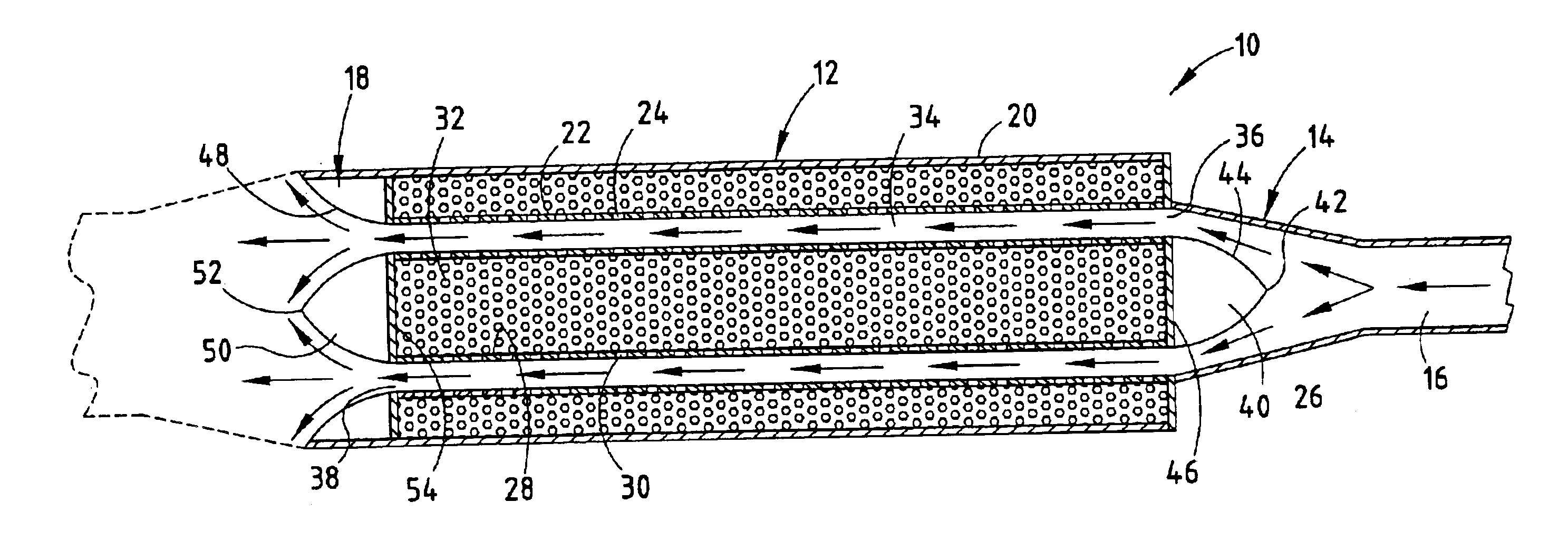
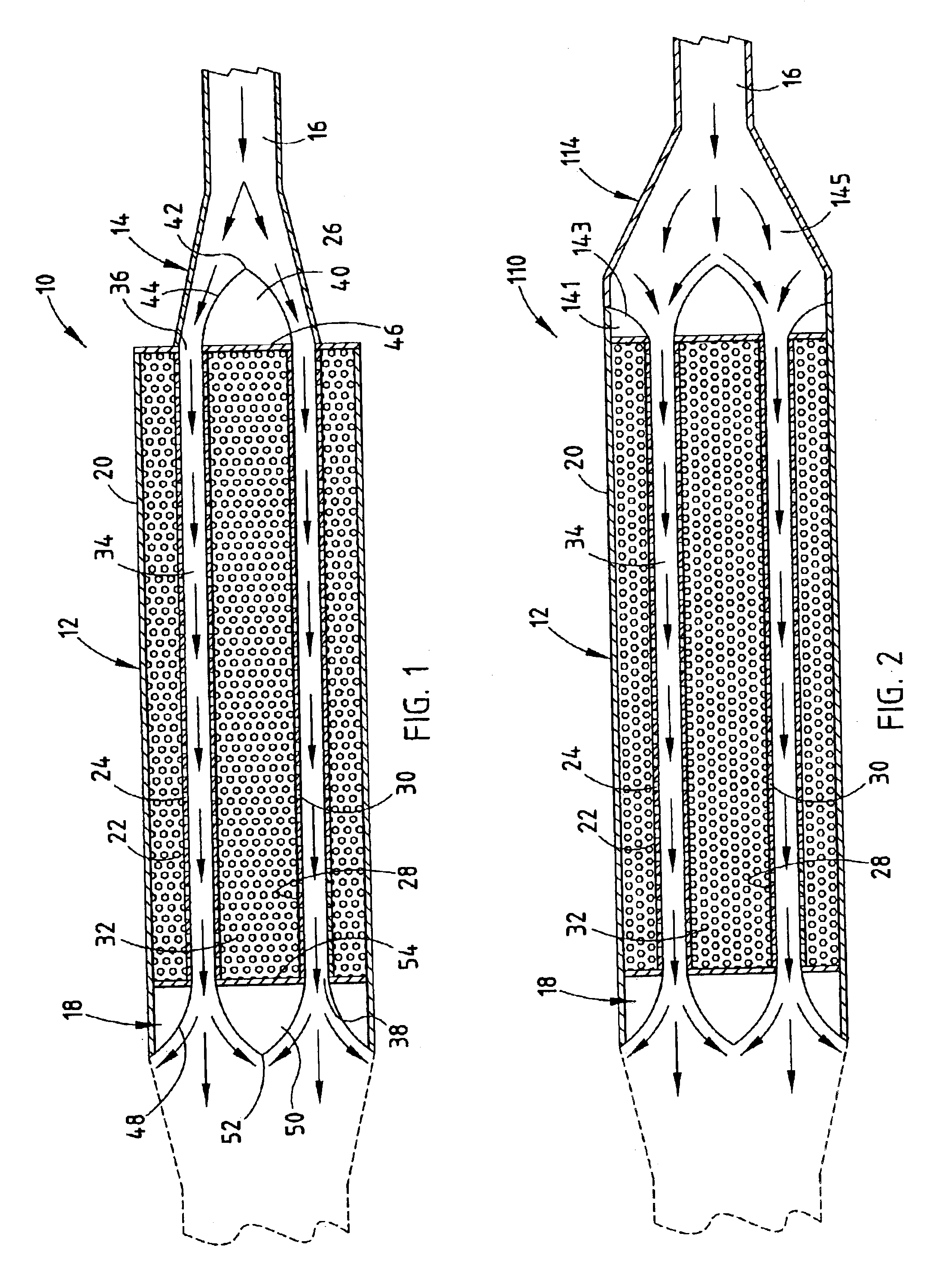
In FIG. 1, there is shown an exhaust system 10 including a muffler section 12, a diffuser section 14 for conveying exhaust gases from a head pipe 16 to the muffler section 12, and an outlet pipe 18 for conveying exhaust gases from the muffler section 12 to the remaining portion or portions of the exhaust system (not shown), which may include other tailpipe sections. The reference to a muffler section 12, diffuser or inlet pipe 14 and an outlet pipe 18 are meant to define functional sections of the exhaust system, and do not necessarily imply separate structural components.

The muffler or silencer section 12 of the exhaust system includes an outer shell 20 having imperforate walls. An intermediate shell 22 having perforated walls defined by perforations 24 is spaced inwardly of the outer shell walls 20. Tapered flow diverters or megaphone sections (discussed later) provide negative pressure pulses toward the engine.

A sound absorbing material 26 is disposed in a first volume defined by...


PUM


Abstract

An improved exhaust system for an internal combustion engine generally comprises two expanding megaphones, separated by a dual core annular flow silencing section. The two or split megaphone design facilitates broadening of the time of the negative pressure wave to provide a desirable broad range power output while substantially reducing obnoxious sound output.

Description

FIELD OF THE INVENTIONThis invention relates to motor vehicle exhaust systems, and more particularly to an exhaust system that employs a sound attenuating device that achieves a combination of improved power output and sound reduction.BACKGROUND OF THE INVENTIONThe exhaust system for an internal combustion engine is designed to perform a plurality of important functions. A primary function of the exhaust system is convey hot exhaust gases away from the engine and discharge the exhaust gases to atmosphere at a location and in a direction away from the operator of the engine. In the case of motorized vehicles, the exhaust gases are preferably discharged from the rear of the vehicle to minimize driver and passenger exposure to the exhaust gases. Another important function of the exhaust system is to silence or muffle hazardous and objectionable noises. However, in general, exhaust systems achieving improved sound dissipation and / or sound absorption do so at the expense of reduced perfo...

Claims


Application Information

Patent Timeline
IPC IPC(8): F01N1/24F01N1/08F01N7/00F01N7/20F01N13/20
CPCF01N1/082F01N13/20F01N1/24
Inventor ZIEHL, JOHN C.
Owner VICIOUS CYCLE PERFORMANCE
Why Eureka
Try Eureka