
Deployable flare with simplified design

Inactive Publication Date: 2005-03-22
AMERICAN TELEPHONE & TELEGRAPH CO
View PDF22 Cites 28 Cited by
  • Summary
  • Abstract
  • Description
  • Claims
  • Application Information

AI Technical Summary

Benefits of technology

The present invention is directed to a further embodiment of the flare that has fewer parts and is more inexpensively manufactured than the first embodiment.
In accordance with a feature of the invention, the detent function is provided by a plurality of fingers, or detents, attached to the inertial component and each extending into a respective recess within a support ring at the front end of the flare. By the time the inertial component has reached its limit of rearward travel, the detents have been completely pulled from recesses and are formed in such a way that they spring to the side at that time so as to be adjacent to a solid face of the support ring rather than facing the opening of, and being aligned with, their respective recesses. The detents are thus prevented from re-entering support ring. Thus once the inertial component has been moved to its displaced position, the detents lock the inertial component in place and prevent it from returning to its original position, thereby maintaining the deployable elements in their outwardly swung position.
In accordance with another feature of the invention, the slide supports, like the detents, are attached to the inertial component. By contrast, the slide supports in the first embodiment are simply wedged in place. The potential disadvantage of the wedged-in-place approach is that the slide supports may fly into other parts of the flare and interfere with its operation or they might interfere with the continuing flight of the projectile or the aft body. Advantageously the slide supports of the present invention remain affixed within the flare after the separation event, precluding any of that from happening. In the present disclosed embodiment, the slide support and detent are parts of an integral slide support / detent component that is threaded through the inertial element with the detent portion extending in the direction of the support ring and the slide support portion extending in the direction of the retaining element. This design advantageously lowers the part count for the flare and helps keep its manufacturing costs low.
In accordance with another feature of the invention, the retaining element is a single part having arms to engage the deployable elements when the flare is in its undeployed configuration, and the retaining element is attached to the aft body. When the aft body is jettisoned, the retaining element is pulled away from the deployable elements, allowing them to open responsive to the movement of the inertial element. By contrast, the retaining element in the first embodiment comprises a ring made up of individual wedge-shaped elements of relatively intricate design that are wedged between the aft body and the projectile and that fall away when the aft body and projectile separate. Here, again, there is the potential for such free-flying parts to interfere with the operation of the flare or with the continuing flight of the projectile or the aft body. The fact that the retaining element of the present embodiment remains connected to the aft body precludes any of that from happening. Moreover, the fact that the retaining element it is a single part of simple design, rather than an assemblage of individual elements of relatively intricate design, again reduces the part count of the flare and contributes to a lower cost of manufacture.
Various hinge pins in the first embodiment are held in place by having a threaded portion that threads into one or the other of the flare's components. The present embodiment, by contrast, uses simple non-threaded pins that are inserted through apertures in the deployable elements and held in place by flaring their ends after insertion. This approach makes assembly of the present embodiment quicker and less labor-intensive.
In addition, the first embodiment has six deployable elements whereas we have discovered that the desired functionality of the flare can be achieved with no more than four deployable elements, again lowering the part count and manufacturing costs.

Problems solved by technology

The potential disadvantage of the wedged-in-place approach is that the slide supports may fly into other parts of the flare and interfere with its operation or they might interfere with the continuing flight of the projectile or the aft body.
Here, again, there is the potential for such free-flying parts to interfere with the operation of the flare or with the continuing flight of the projectile or the aft body.

Method used


Image

  • Deployable flare with simplified design
  • Deployable flare with simplified design
  • Deployable flare with simplified design

Examples


Embodiment Construction

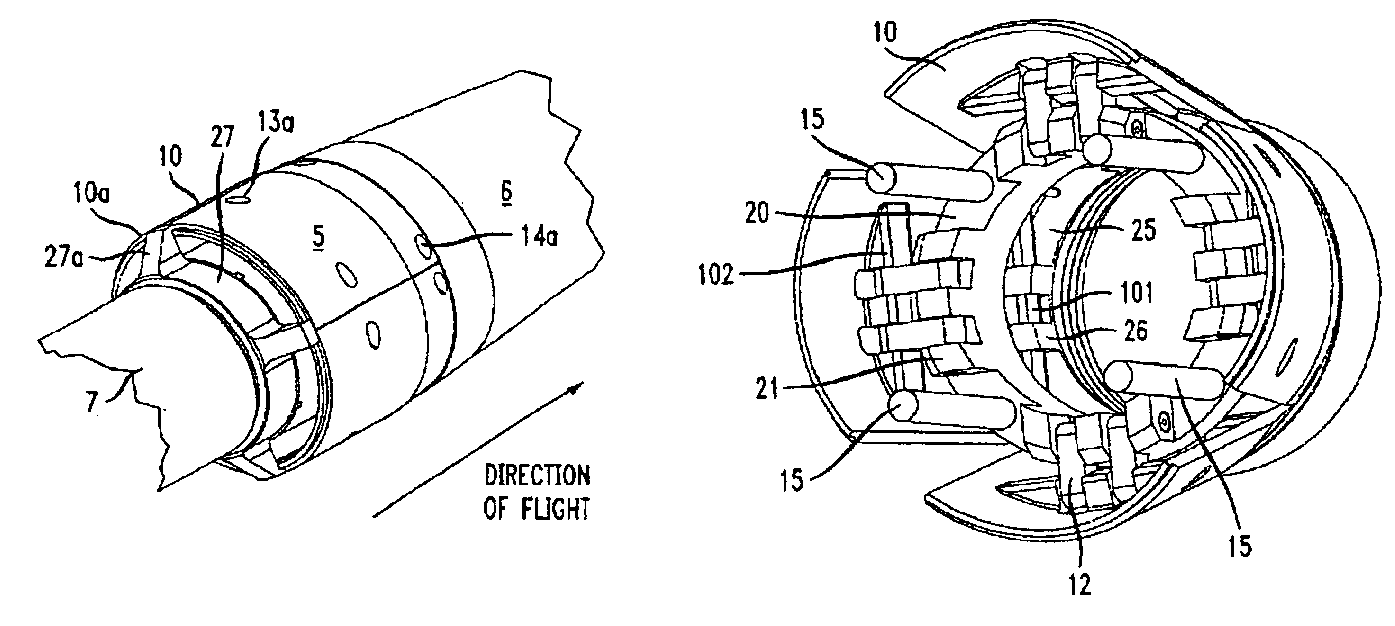
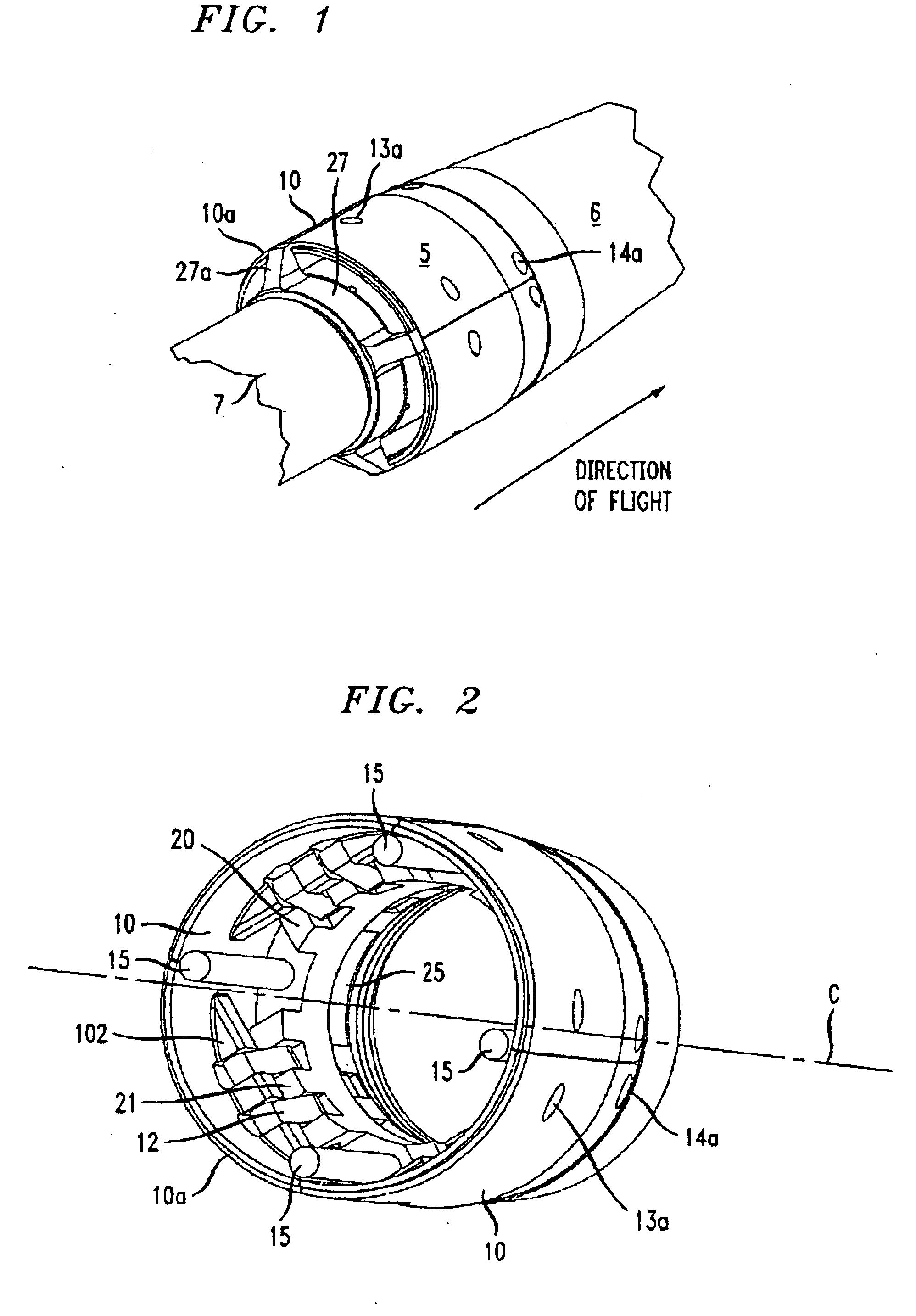
FIG. 1 shows a flare 5 embodying the principles of the present invention attached to a projectile 6 whose intended direction of flight is as shown. An aft body 7 extends through the center of flare 5 and is attached to the internal body of projectile 6.

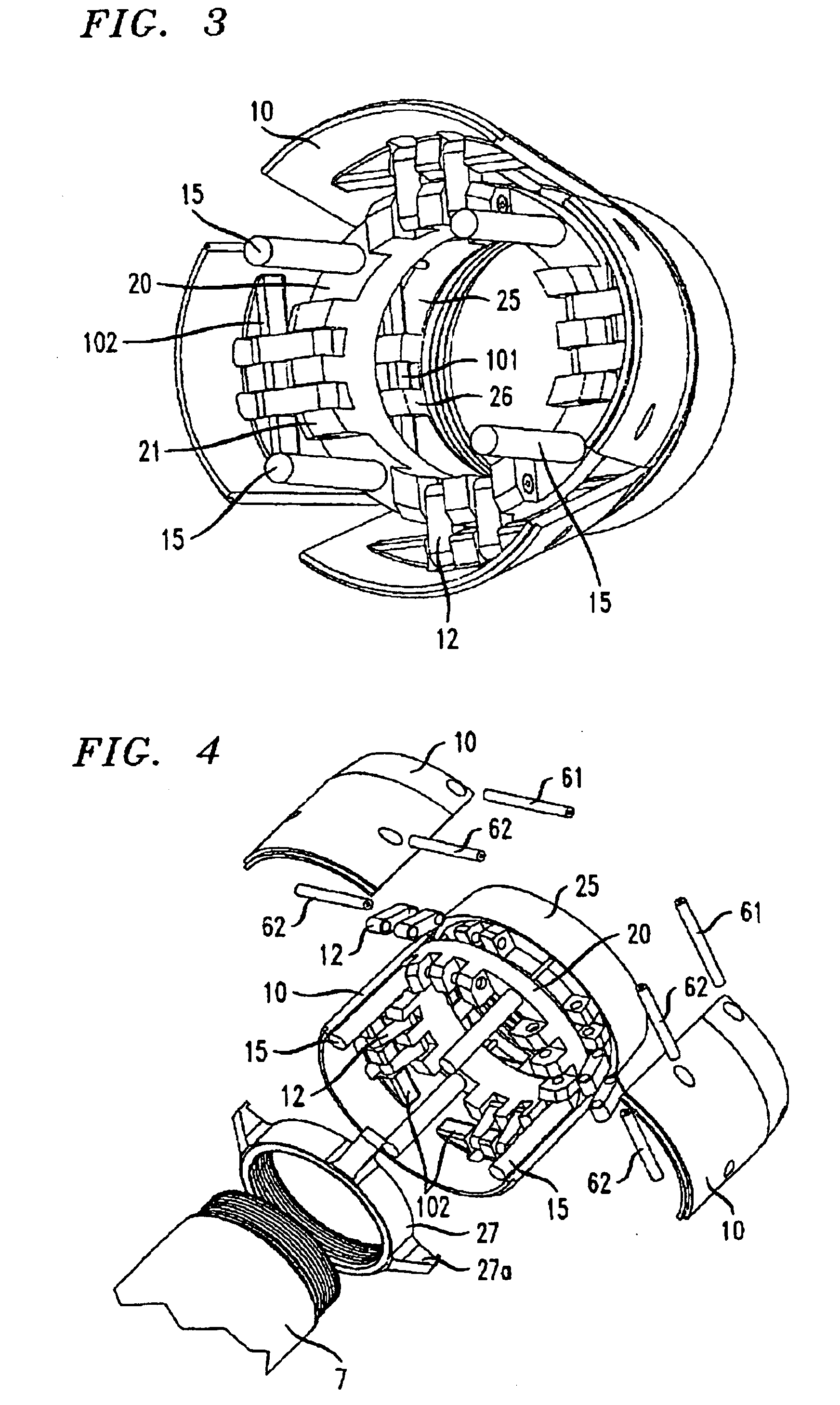
The construction of flare 5 can be seen in FIGS. 2 through 4. The flare includes a threaded support ring 25 that threads onto projectile 6, with an aft portion of projectile 6 (not shown) extending through the center of the flare. Attached to support ring 25 are four petals 10 arrayed in a first position around central axis C of the flare. Petals 10 are each in the form of a cylindrical segment whose side edges meet to form a cylinder whose central axis is coincident with said axis of the flare.

A detailed view of one of the petals 10 is shown in FIG. 5. A hinge element 101 is disposed on the inside surface of petal 10 near its forward edge. The hinge element 101 of each petal mates with a corresponding hinge element 26 attached to sup...


PUM


Abstract

The center of pressure of a projectile is caused to move upon the occurrence of an event that changes the static margin, such as the jettisoning of a body previously attached to the projectile, as noted above. In particular embodiments, this is achieved by a flare disposed toward the rear of the projectile. The flare has petals that deploy from a first, stowed position to a second, deployed position upon the occurrence of the event. In the stowed position, the petals are aligned with the air stream, in order to minimize drag. In the deployed position, the petals project into the air stream in such a way as to move the lift center rearward. A slide ring within the flare has sufficient inertia that it shifts aft in response to an acceleration that occurs when the attached body and the projectile are separated from one another. The slide ring is linked to the petals in such a way that the petals are deployed by the displacement of the slide ring. Detents lock the slide ring in its displaced position.

Description

BACKGROUND OF THE INVENTIONThe present invention relates to the stabilization of projectiles in flight.The invention more particularly relates to the aerodynamic stabilization of projectiles of a type that, during flight, are designed to jettison either a forward or an aft body that was connected to the projectile when it was initially launched, as from a gun or a missile. Those skilled in the art are well aware of the context or contexts in which such a mode of operation occurs.Aerodynamic stabilization of a projectile in flight, i.e., preventing it from tumbling, is achieved by making the center of the lifting forces, also referred to as the center of pressure, lie behind the center of mass. The distance between these centers and divided by the total projectile length is called the static margin. Even if the projectile is stable when launched, its static margin may sufficiently change after the body that was attached to it is jettisoned that the static margin is no longer sufficie...

Claims


Application Information

Patent Timeline
IPC IPC(8): F42B10/50F42B10/00
CPCF42B10/50
Inventor CARLYLE, JOHN DARYLHALL, WILLIAMKING, HARTLEY HUGHESMENNA, THOMAS LOUISROMERO, LAWRENCE STEVEN
Owner AMERICAN TELEPHONE & TELEGRAPH CO
Learn More