
Anti-drawback medical valve

Inactive Publication Date: 2005-03-22
NP MEDICAL
View PDF162 Cites 130 Cited by
  • Summary
  • Abstract
  • Description
  • Claims
  • Application Information

AI Technical Summary

Benefits of technology

In accordance with one aspect of the invention, a medical valve has an open mode that permits fluid flow, and a closed mode that prevents fluid flow. Among other things, the medical valve includes a housing forming an interior

Problems solved by technology

Problems arise, however, when the syringe is withdrawn from the valve.
Specifically, a back pressure (i.e., a proximally directed pressure) produced by the withdrawing syringe undesirably can cause blood to be drawn proximally into the valve.
In addition to coagulating and impeding the mechanical operation of the valve, blood in the valve also compromises the sterility of the valve.

Method used


Image

  • Anti-drawback medical valve
  • Anti-drawback medical valve
  • Anti-drawback medical valve

Examples


Embodiment Construction

In illustrative embodiments, a medical valve is configured to reduce drawback to relatively negligible volumes. Details are discussed below.

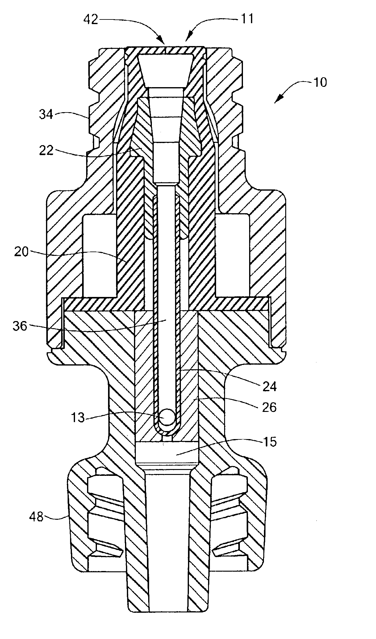
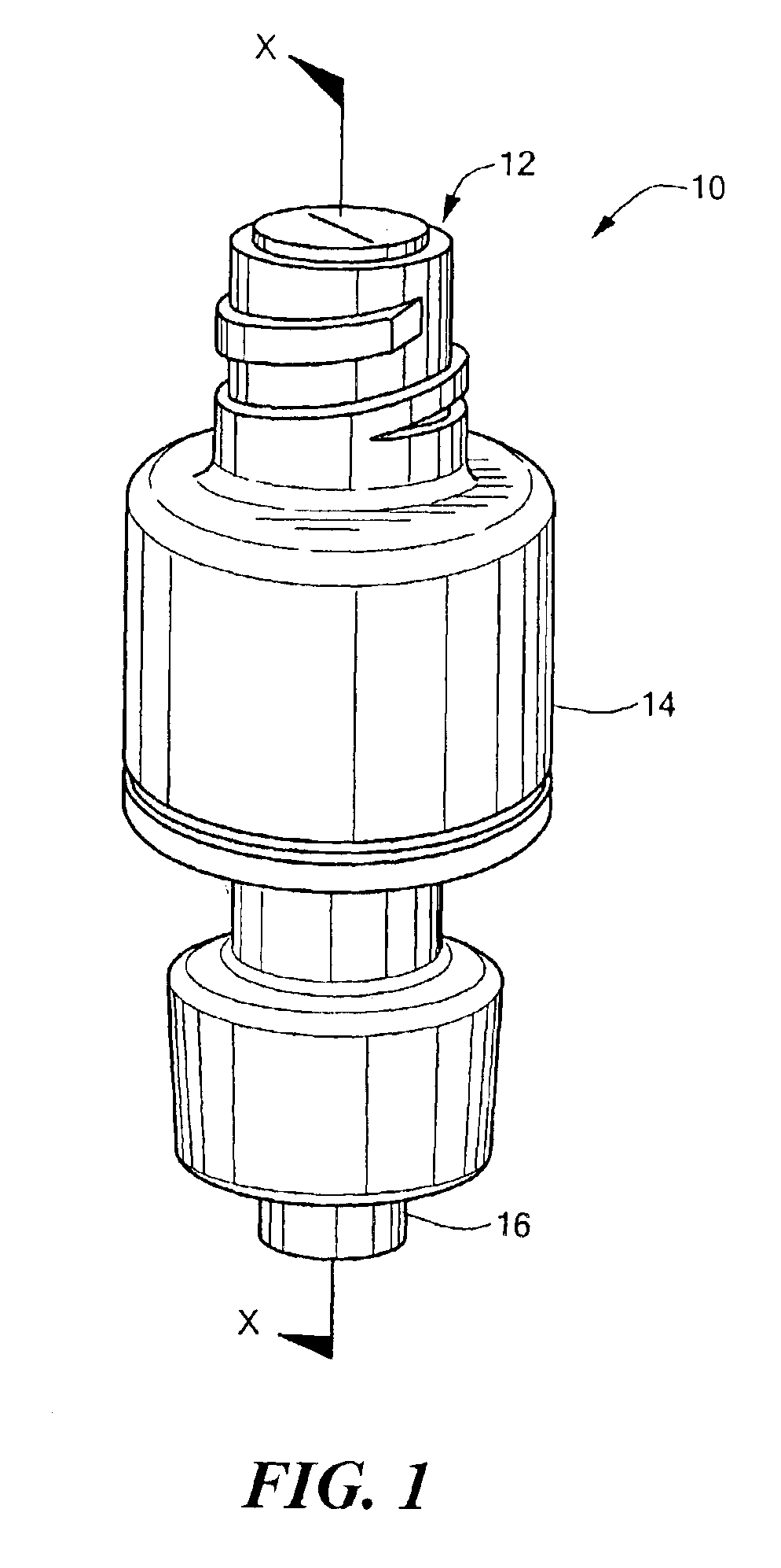
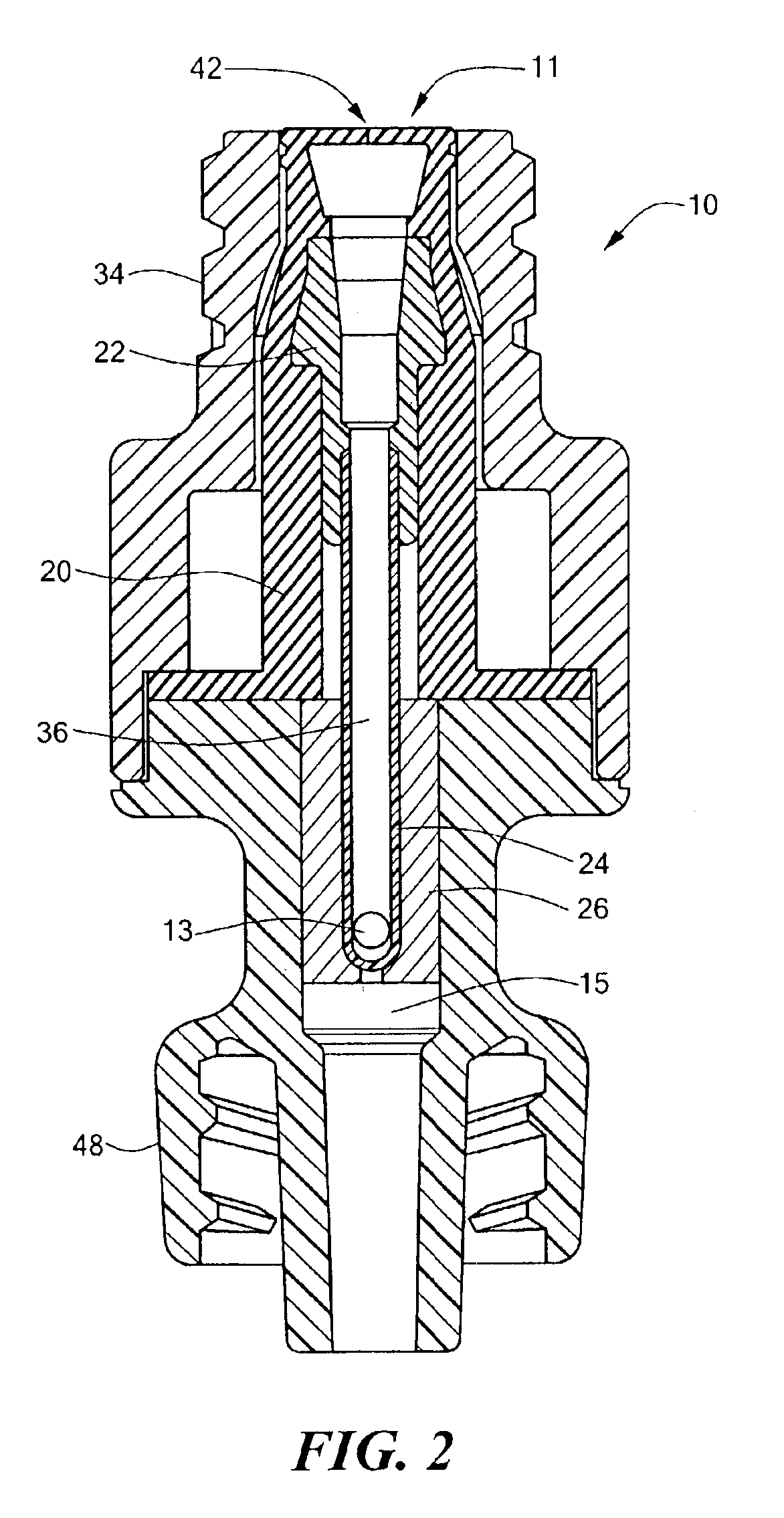
FIG. 1 schematically shows a medical valve 10 that is configured to reduce fluid drawback (a / k / a “back-flow”) when a syringe or other type of nozzle is withdrawn from it. The valve 10 includes a proximal port 12 for receiving the nozzle, a valve body 14 having an internal valve mechanism (shown in FIG. 2) that controls fluid flow through the valve 10, and a distal port 16 for directing fluid between the valve 10 and a patient. The distal port 16 of the valve 10 may be at its location shown in FIG. 1, or at a location that is orthogonal to the longitudinal dimension of the valve 10. The fluid preferably is in liquid form, such as liquid medication. Although much of the discussion herein refers to the proximal port 12 as a fluid inlet, and the distal port 16 as a fluid outlet, the proximal and distal ports 12 and 16 also may be respectively utiliz...


PUM


Abstract

A medical valve has an open mode that permits fluid flow, and a closed mode that prevents fluid flow. Among other things, the medical valve includes a housing forming an interior having a fluid chamber, and a valve mechanism within the interior. The valve mechanism has a movable member that includes a needle (e.g., a hypetube). The needle may extend into the fluid chamber when the valve is in the open mode.

Description

FIELD OF THE INVENTIONThe invention generally relates to medical products and, more particularly, the invention relates to devices for reducing backflow through a medical valve.BACKGROUND OF THE INVENTIONIn general terms, medical valving devices often act as a sealed port that may be repeatedly accessed to non-invasively inject fluid into (or withdraw fluid from) a patient's vasculature. Consequently, a medical valve permits the patient's vasculature to be freely accessed without requiring such patient's skin be repeatedly pierced by a needle.Medical personnel insert a syringe into the medical valve to inject fluid into (or withdraw fluid from) a patient who has an appropriately secured medical valve. Once inserted, fluid may be freely injected into or withdrawn from the patient. Problems arise, however, when the syringe is withdrawn from the valve. Specifically, a back pressure (i.e., a proximally directed pressure) produced by the withdrawing syringe undesirably can cause blood to...

Claims


Application Information

Patent Timeline
IPC IPC(8): A61M39/02A61M39/26A61M39/04A61M39/00A61M25/16A61M25/18
CPCA61M39/045A61M39/26Y10S604/905A61M2039/263A61M2039/262A61M2039/267
Inventor GANEM, CHARLES F.
Owner NP MEDICAL
Learn More