
Duct for cables

a cable and duct technology, applied in the direction of mechanical equipment, other domestic objects, machine supports, etc., can solve the problems of reducing mechanical resistance, reducing the dimensions of the duct and the load that it is able to withstand, and certain critical factors and some not entirely satisfactory technical aspects, so as to improve mechanical performance and optimize functional performance.

Inactive Publication Date: 2005-03-22
ABB SPA
View PDF6 Cites 3 Cited by
  • Summary
  • Abstract
  • Description
  • Claims
  • Application Information

AI Technical Summary

Benefits of technology

A primary task of the present invention is to provide a duct that will enable the drawbacks of the known art to be overcome, and in particular that will enable improved mechanical performance, together with optimized functional performance.
In the context of this task, a purpose of the present invention is to provide a duct for electrical cables which, as compared to the known solutions, may be produced in a simplified way.
Another purpose of the present invention is to provide a duct that will enable simplification of the operations of installation, reducing the components that have to be used during positioning in place.
Yet another purpose of the present invention is to provide a duct the structure of which will be such as to minimize, if not prevent completely, any possible damage to the cables or injury to the installers.
A further purpose of the present invention is to provide a duct that will enable considerable simplification of the steps of installation of the duct itself, for example in terms of useful length required, and will facilitate connections / disconnections between the parts or between a number of different ducts, thus reducing also the time required for positioning in operation.
Not the least important purpose of the present invention is to provide a duct that will present high reliability, relatively ease of fabrication and competitive costs.

Problems solved by technology

Notwithstanding this, the intrinsic structure of the above ducts, if on the one hand it is the principal reason for their commercial success, on the other hand, it is at the same time the source of certain critical factors and some not altogether satisfactory technical aspects.
In particular, the extreme essentiality of implementation results in a normally modest structural rigidity and in practice in a reduced mechanical resistance to loading; this clearly limits the dimensions of the duct and the loads that it is able to withstand, which, if they are excessive, could lead to problems of bending or even to deformation.
The above different solutions, albeit valid, in general adversely affect, at least partially, the advantages afforded by such ducts in that the production costs increase on account of the use of additional pieces or of the adoption of particular production processes, and / or the difficulties of installation are increased.
It is necessary, in fact, to consider that usually the channels are arranged in positions that are not particularly convenient to reach and in narrow spaces, and hence the use of supports or jointing devices is not always easy.
Another critical factor of wire-mesh ducts of a known type is represented by the fact that the ends of the weft wires are normally exposed and have sharp edges that during positioning may either damage the cables or cause injury to the installers.
Furthermore, on account of these sharp edges, the coupling of the ducts with the cover is problematical, and the cover itself may even suffer damage.
Also these solutions, albeit effective, have, however, adverse repercussions on the costs of production and of laying in place.
Finally, the process of welding between the wires itself, taking into account also the substantial number of junction points, is not altogether satisfactory since it is necessary to resort to welding methods, typically induction welding, which are in themselves critical and entail the use of complex and costly equipment

Method used


Image

  • Duct for cables
  • Duct for cables
  • Duct for cables

Examples


Embodiment Construction

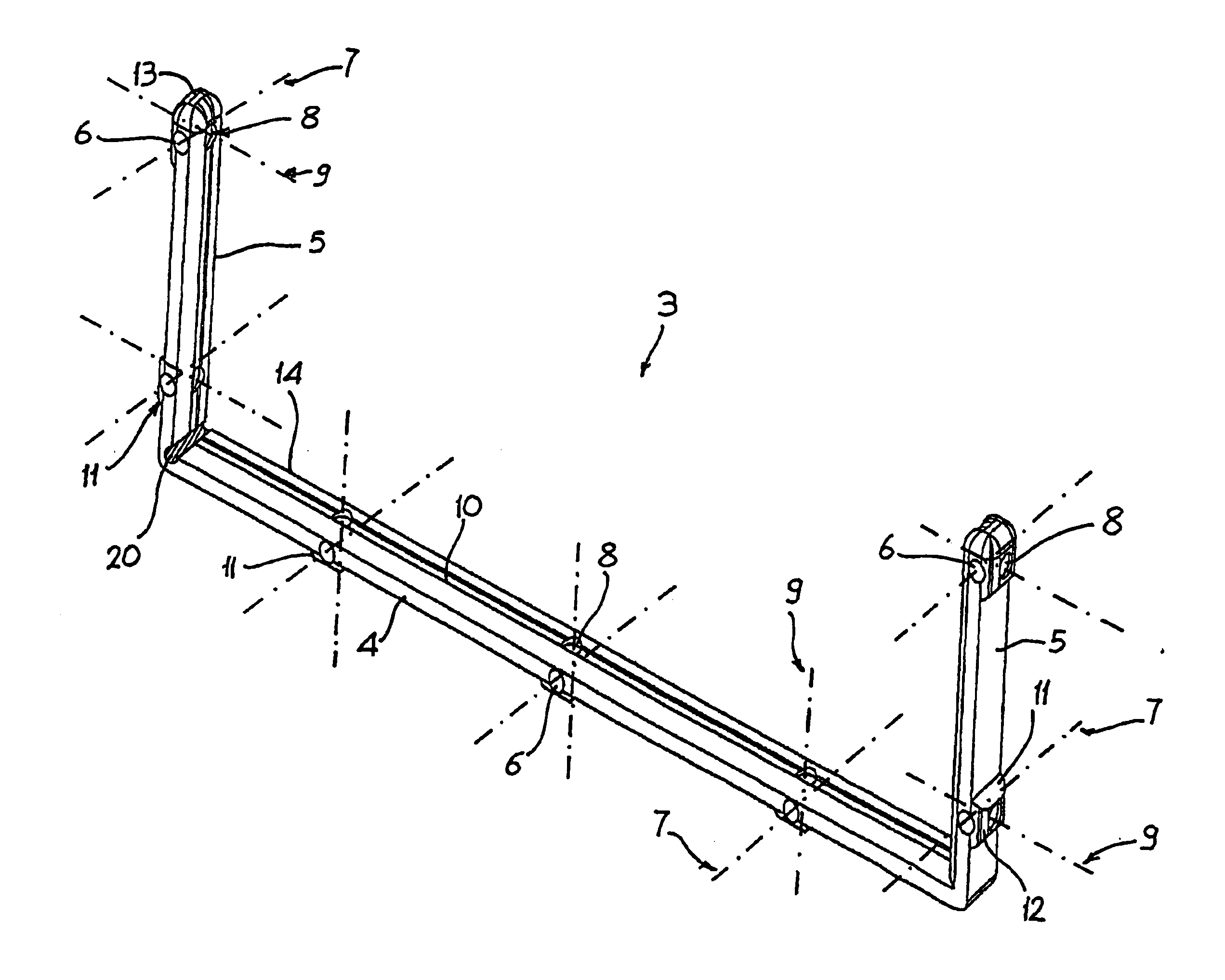
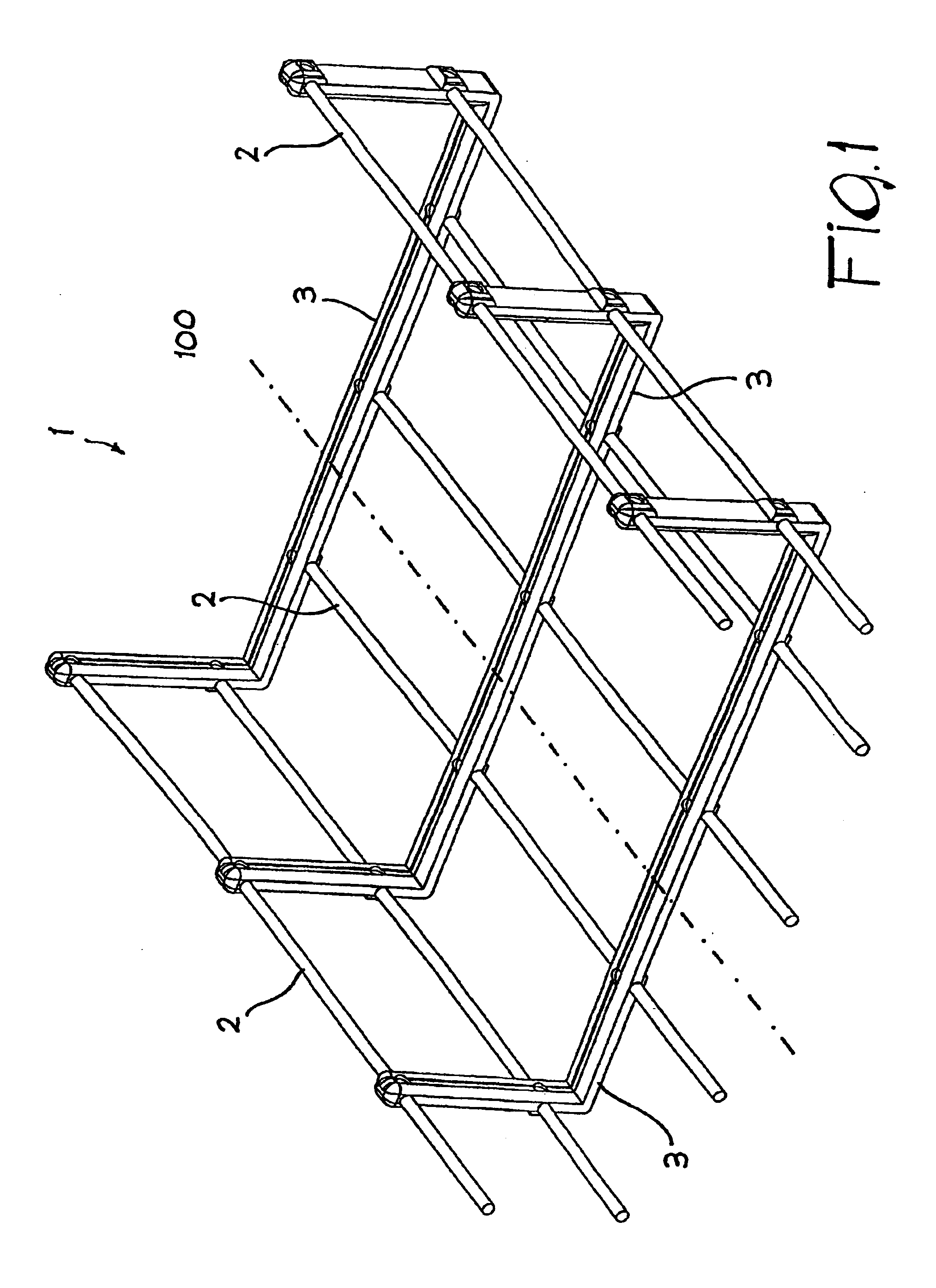
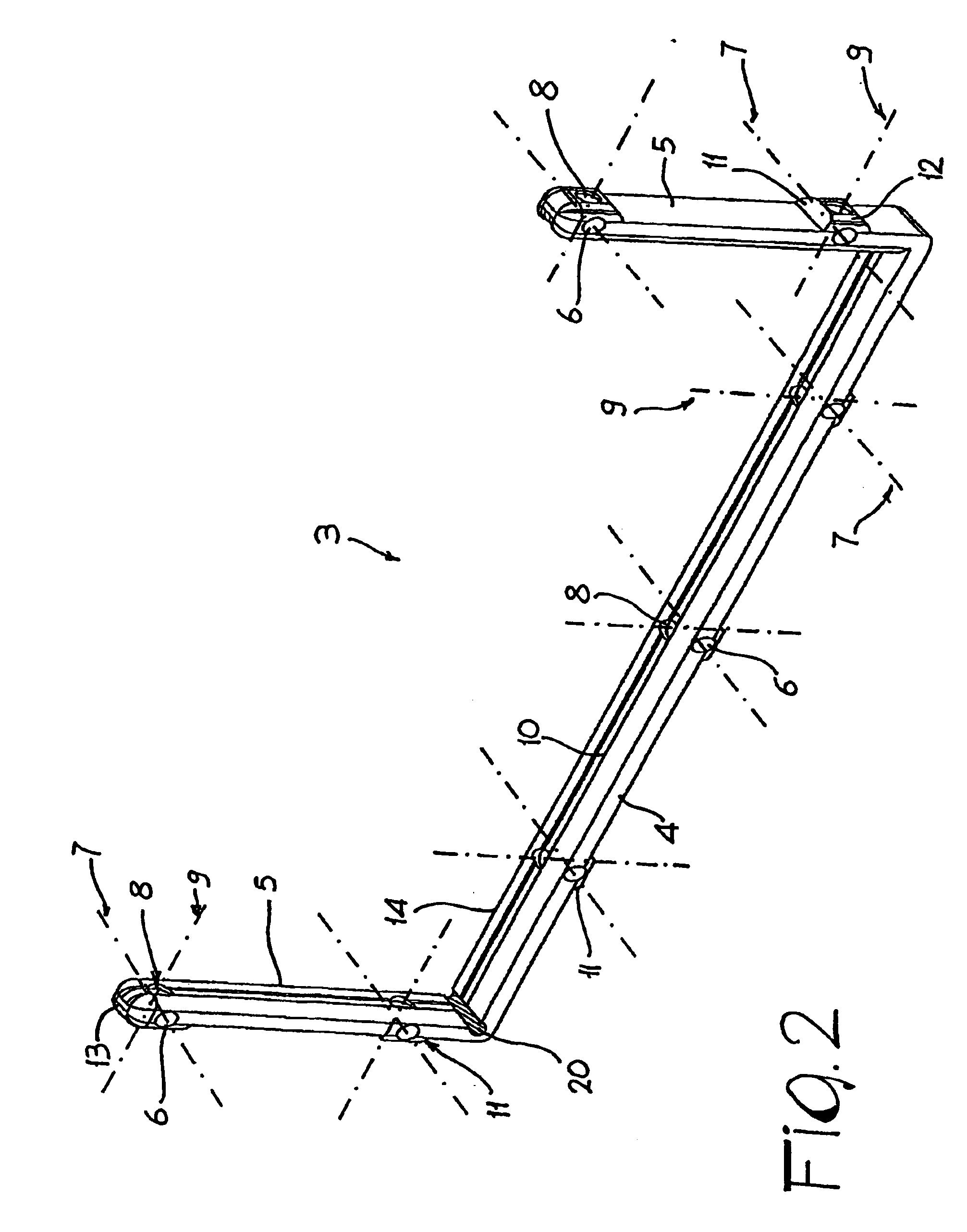
With reference to the figures referred to above, the duct for cables according to the invention, defined as a whole by the reference number 1, comprises a plurality of filiform metal elements 2 arranged substantially parallel to one another, which extend, in a rectilinear or quasi-rectilinear way, in the direction of longitudinal development of the duct, designated in FIG. 1 by the reference axis 100. In the embodiment illustrated in FIG. 1, the filiform elements 2 are constituted generally by metal wire with circular cross section; alternatively, and in an altogether equivalent way, the filiform elements 2 could be made with a different cross section, for example square, rectangular, or still other shapes provided that they are compatible with the application.

Advantageously, the duct for cables 1 comprises, for at least a portion of its development in length, a plurality of structural modules 3, operatively associated to the, filiform elements 2 according to the modalities which wi...


PUM


Abstract

A duct for electrical cables comprises a plurality of filiform elements arranged substantially parallel to one another according to the longitudinal development of the duct. The duct of the invention includes, for at least a portion of its length, a plurality of structural modules, which are arranged in a transverse direction with respect to said filiform elements and are set at a distance from one another in succession according to the longitudinal development of the duct. The supporting modules have a basically U-shaped body that includes a central wall from which there project, on opposites sides with respect to one another, two side walls that are set substantially parallel to one another. On said shaped body coupling means, designed to enable connection with said filiform elements, are arranged.

Description

FIELD OF THE INVENTIONThe present invention relates to a duct for cables, in particular to a duct, or raceway, for electrical cables having an improved structure and performance. In particular, the present invention relates to a duct of the wire-mesh type referred to normally in the art by the terms wire-mesh / mesh-cable-tray or mesh-cable-duct, or mesh-cable-trellis.BACKGROUND OF THE INVENTIONAs is known, in many buildings, whether these be for industrial use, or for use in the handicrafts, commercial or residential sectors, for example factories, workshops, hospitals, hotels, tenement blocks, individual dwellings, shops, trading centres, etc., there are currently used in an increasingly extensive way more or less complex wiring systems that enable transmission of different types of signals to the various parts of the building, for example transmission and distribution of electricity, telecommunications, computer systems, various systems for protection and control, and so forth.In s...

Claims


Application Information

Patent Timeline
IPC IPC(8): H02G3/04
CPCH02G3/0443
Inventor MORINI, GIUSEPPEFONTANA, RODOLFO
Owner ABB SPA
Learn More