Electric motor

a technology of electric motors and motors, applied in the direction of electric generators/motors, dynamo-electric machines, rotary current collectors, etc., can solve the problems of no cooling air flow from the fan and big impediment to cooling

Inactive Publication Date: 2005-03-22
JOHNSON ELECTRIC SA
View PDF10 Cites 11 Cited by
  • Summary
  • Abstract
  • Description
  • Claims
  • Application Information

AI Technical Summary

Problems solved by technology

Commutator mounted fans are made of more expensive thermoset plastic to withstand the high temperatures of the commutator which can be especially high under stall conditions when the rotor is locked, resulting in no cooling air flow from the fan.
The terminal portion, however, provides a big impediment to cooling air flow across the commutator surface generated by a fan fixed to the rotor core due to the physical size and location of the terminal portion.

Method used


Image

  • Electric motor
  • Electric motor
  • Electric motor

Examples


Embodiment Construction

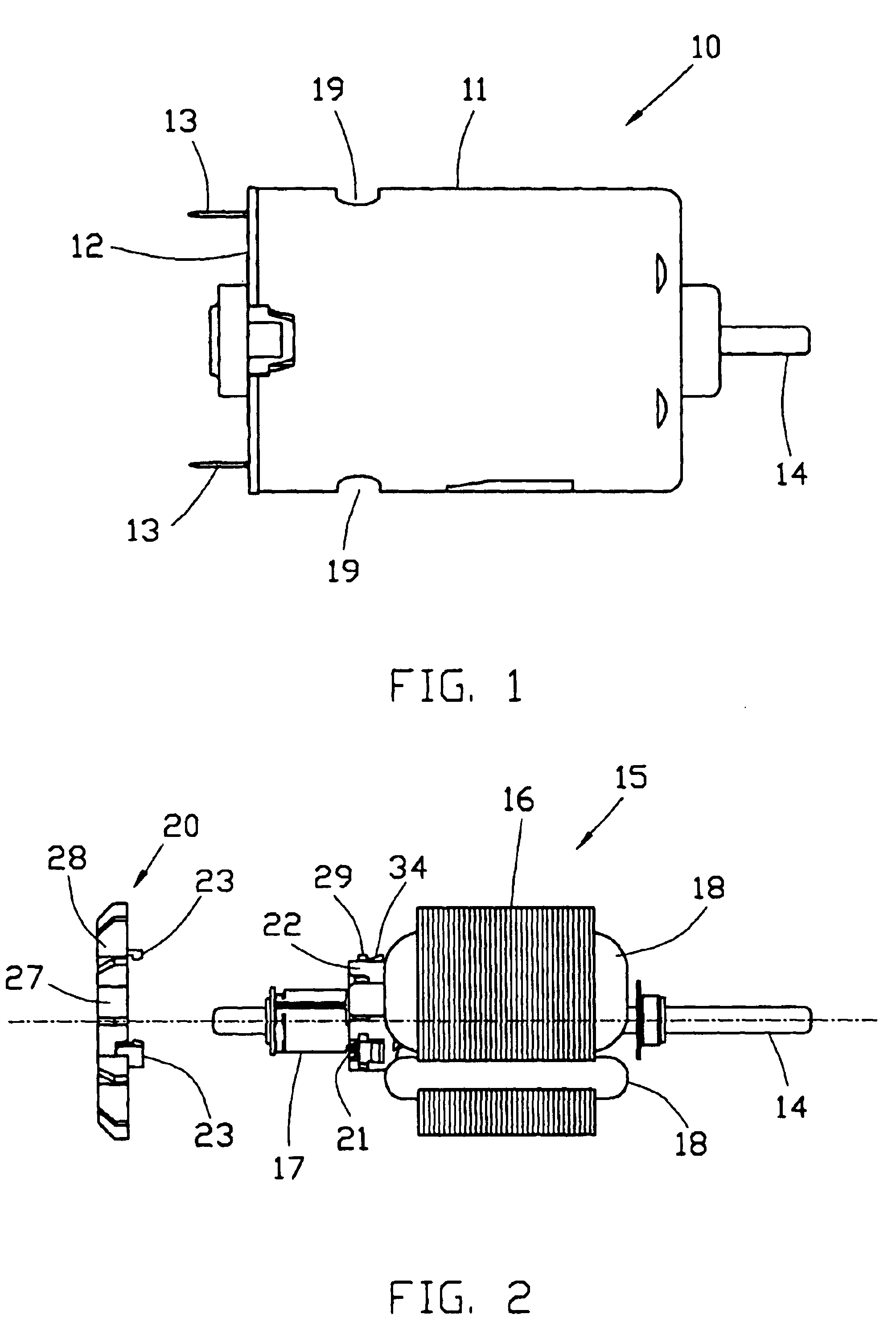
FIG. 1 shows, in side view, a small PMDC motor 10 representing the preferred embodiment of the invention. The motor has a deep drawn metal rear housing 11 supporting a permanent magnet stator. The open end of the housing is closed by an end cap 12 which supports motor terminals 13 and brushes. The housing 11 has ventilation apertures 19. A wound rotor or armature cooperates with the stator. The motor has a shaft 14 journalled in bearings fitted to the end cap 12 and closed end of the housing.

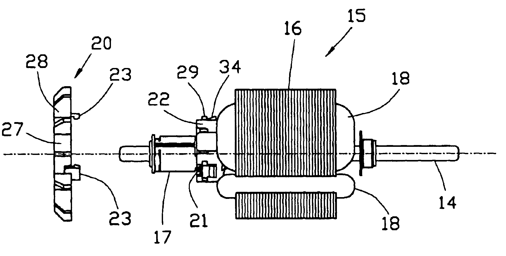
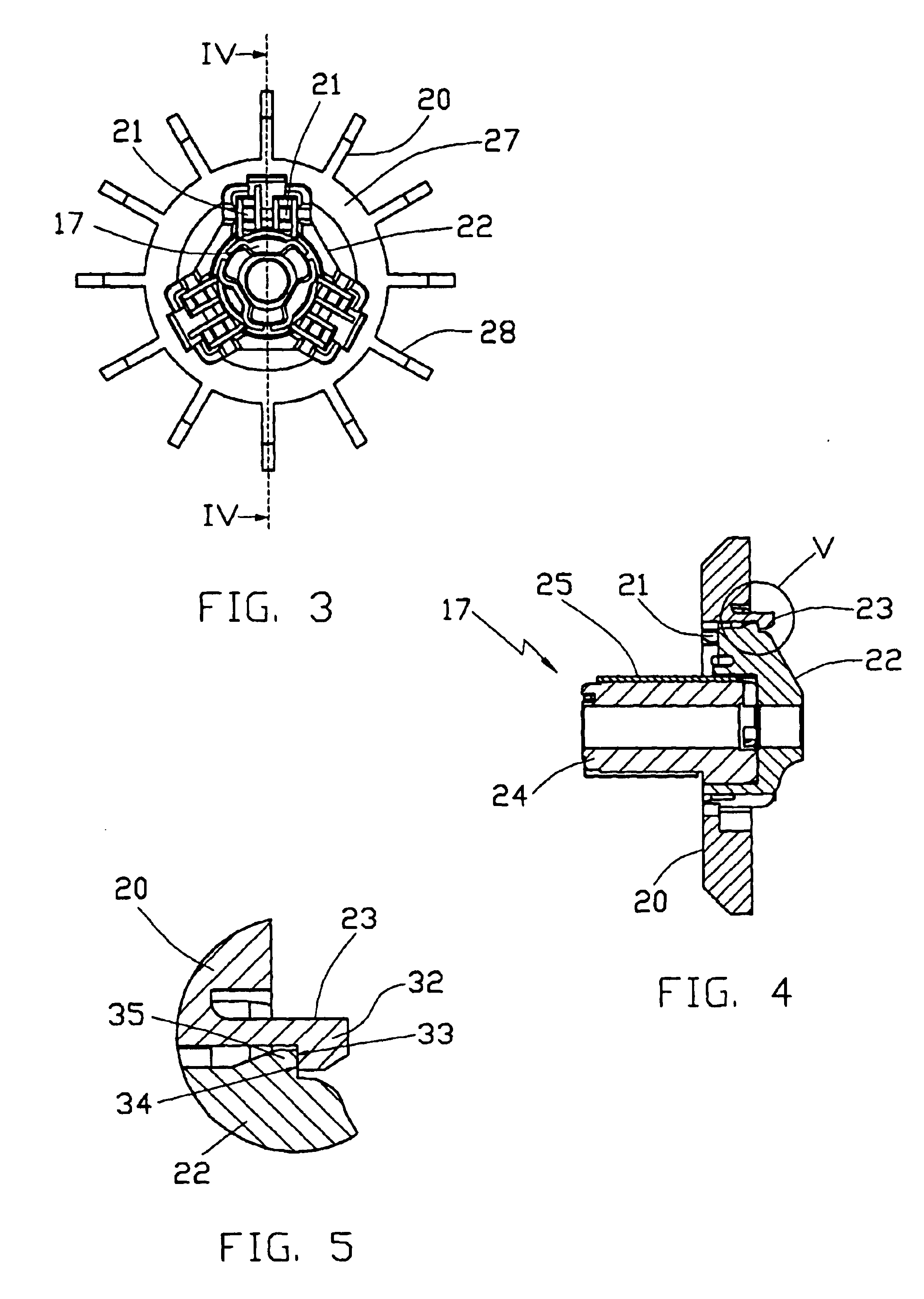
The rotor 15 is shown in FIG. 2. The rotor 15 comprises rotor core 16 mounted on the shaft 14. A commutator 17 is mounted on the shaft 14 at one end of the core 16 adjacent the end cap 12 so that the brushes make sliding contact with the commutator 17. Windings 18 are wound around poles of the rotor core 16 and electrically terminated on the commutator 17. A fan 20 is fitted to the commutator 17.

As shown in FIG. 2, the fan 20 is fitted to the commutator 17 after the rotor 15 has been wound. This...


PUM


Abstract

A miniature PMDC motor has a wound rotor 15 comprising a rotor core 16 and a commutator 17 mounted on a shaft 14. A cooling fan 20 is directly mounted onto the commutator 17 by use of a mechanical snap-fit type connection. Projections 29 on the commutator mate with recesses in the fan 20 to prevent relative rotational movement and detents including resilient fingers 23 and projection surfaces 34 hold the fan axially.

Description

This nonprovisional application claims priority under 35 U.S.C. § 119(a) on Patent Appication No(s). 0218198.0 filed in Great Britain on Aug. 6, 2002, which is (are) herein incorporated by reference.BACKGROUND OF THE INVENTIONThis invention relates to electric motors and in particular, to a miniature electric motor having an internal cooling fan.Miniature electric motors with internal cooling fans are well known with the fan providing a source of cooling air flow through the motor so that the motor can run at a higher current rating or power than it could be otherwise.In a miniature electric motor, and in particular, miniature PMDC motors with wound rotors, the fans are attached directly to the armature core, as shown in GB 2189944 for example or they may be mounted directly onto the commutator about the terminals or tangs. Commutator mounted fans are made of more expensive thermoset plastic to withstand the high temperatures of the commutator which can be especially high under stal...

Claims


Application Information

Patent Timeline
Patent Type & Authority Patents(United States)
IPC IPC(8): H02K9/06H02K9/04H02K13/00
CPCH02K9/06H02K13/006
Inventor HO, SEUNG PUNYUEN, CHI WAI DEREK
Owner JOHNSON ELECTRIC SA
Why Eureka
Try Eureka