Self-calibrating electrical test probe

a test probe and self-calibrating technology, applied in the field of electric test probes, can solve the problems of inability to accurately place future connections, and inability to remove the probing head b>20/b> from the electrical component b>28/b>

Inactive Publication Date: 2005-03-22
TELEDYNE LECROY
View PDF7 Cites 90 Cited by
  • Summary
  • Abstract
  • Description
  • Claims
  • Application Information

AI Technical Summary

Benefits of technology

The foregoing and other objectives, features, and advantages of the inve

Problems solved by technology

Removing and replacing a probing head 20 from an electrical component 28 is problematic because it is often difficult and/or time consuming to accurately place, position, and hold the probing head 20 on the electrical component 28.
Future connections, therefore, would not be as accurate because the contact would not be as complete.
Removing the probing head 20 from the electrical component 28, therefore,

Method used


Image

  • Self-calibrating electrical test probe
  • Self-calibrating electrical test probe
  • Self-calibrating electrical test probe

Examples


Embodiment Construction

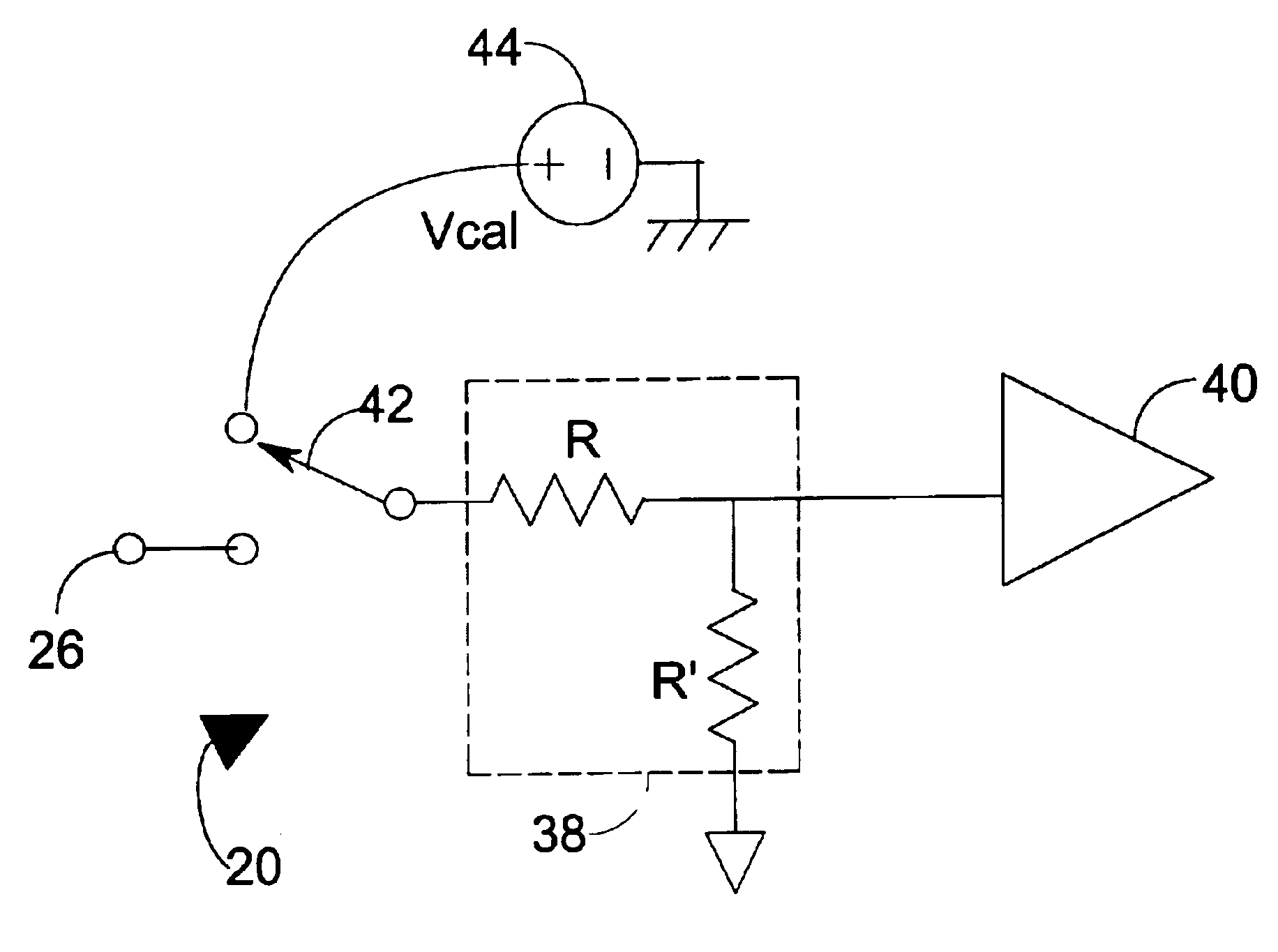
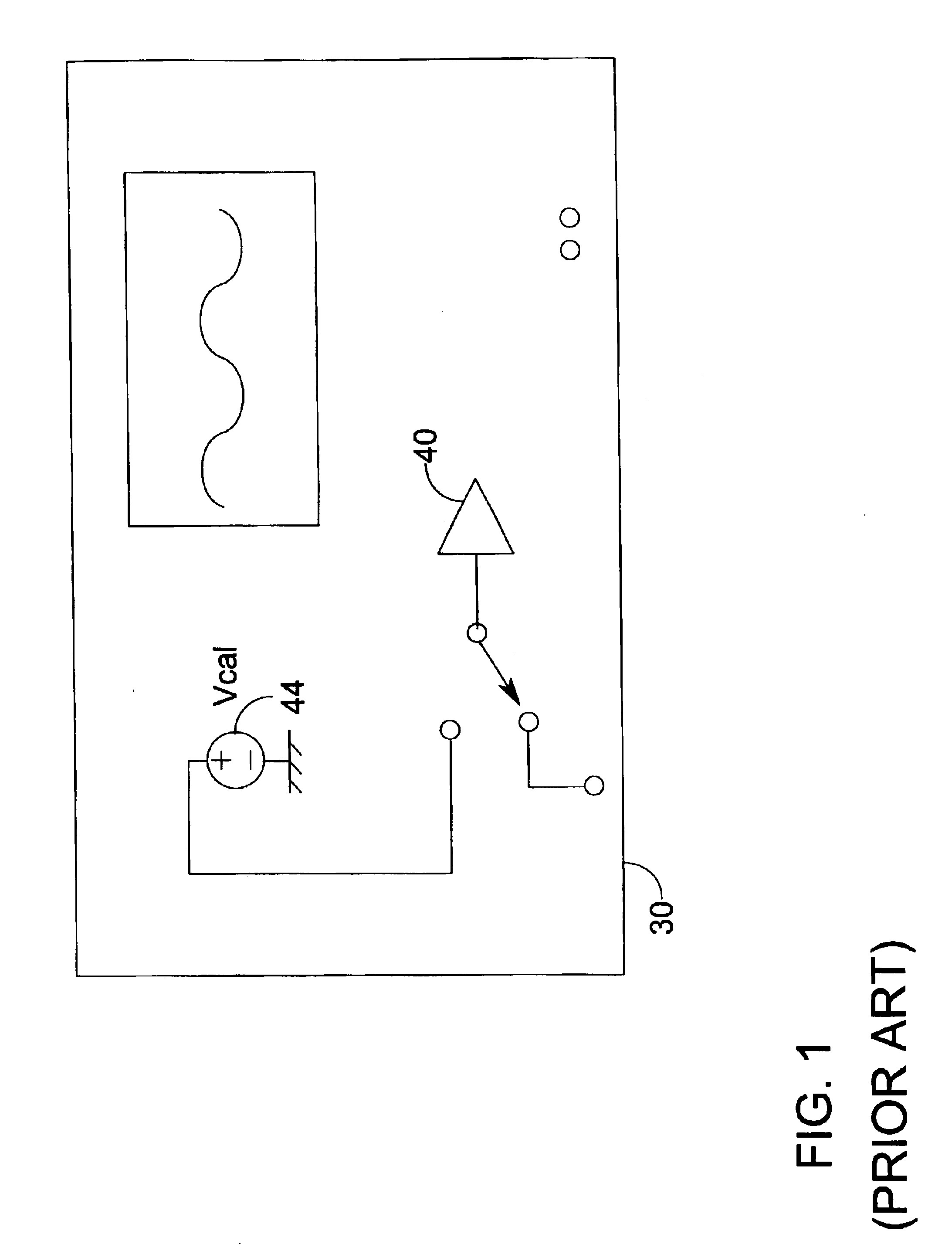
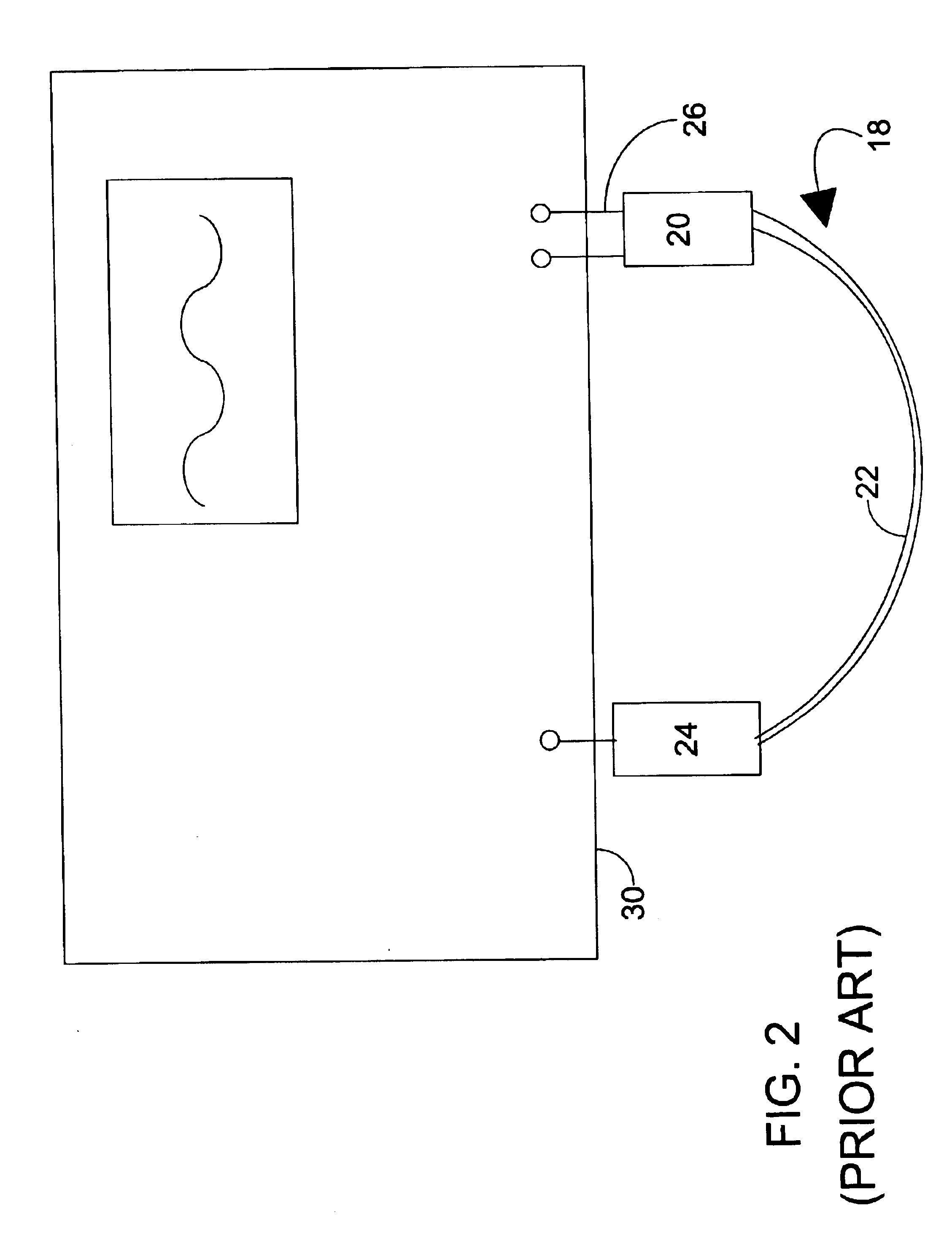
The present invention is directed to a self-calibrating test probe system. Using the system of the present invention, the test probe 18 may be calibrated or may self-calibrate while the probing head 20 remains connected to an electrical component (or circuit) 28 under test. Further, in one preferred embodiment of the system of the present invention, the entire system (including the test probe 18 and a testing instrument 30) may be calibrated or may self-calibrate while the probing head 20 remains connected to an electrical component 28 under test. Because the test probe 18 may remain connected during this process, the necessity of having to remove the probing head 20 from the electrical component 28 and then replace the probing head 20 on the electrical component 28 is eliminated. Eliminating the need to remove and replace the probing head 20 eliminates significant problems including added time, possible misconnections, poor connections with the contact, and other undesirable conseq...


PUM


Abstract

A self-calibrating test probe system of the present invention does not require probing head removal and replacement. Using the system of the present invention, the test probe and/or the entire system (including a testing instrument) may be calibrated or may self-calibrate while the probing head remains connected to an electrical component under test. The self-calibrating electrical testing probe system includes calibration circuitry including at least one input resistor, at least one relay, and at least one known calibration reference signal. If the test probe is an active test probe, the calibration circuitry may also include at least one amplifier. Each relay has a first position that provides signal access to a testing signal from an electrical component under test and a second position that provides signal access to the known calibration reference signal. Using the present invention, the error of the test probe and/or system is determined and compensated. Exemplary methods by which error compensation may be provided includes, for example, amplifying the testing signal, creating a correction table of correction values and adding an appropriate value from the correction table, or mathematically compensating.

Description

The present application is a nonprovisional of U.S. Provisional Patent Application Ser. No. 60 / 340,496, filed Dec. 14, 2001. The present application is based on and claims priority from this provisional application, the disclosure of which is hereby incorporated herein by reference.BACKGROUND OF INVENTIONThe present invention relates generally to electrical test probes for making contact between electrical components and testing instruments and, more specifically to a self-calibrating differential electrical testing probe.An electrical test probe 18 generally consists of a probing head 20, a cable 22, and a scope interface (hereinafter, “connector 24”). The probing head 20 may have an integral or replaceable probing tip 26 or other test probe input that is suitable for making an electronic contact with electrical components. The probing head 20 is attached to a first end of the cable 22 and the connector 24 is attached to a second, opposite end of the cable 22.Test probes are often ...

Claims


Application Information

Patent Timeline
IPC IPC(8): G01R1/067G01R35/00
CPCG01R35/005G01R1/06788
Inventor SEKEL, STEPHEN MARK
Owner TELEDYNE LECROY
Why Eureka
Try Eureka