
Process for identifying abnormalities in power transformers

a technology for abnormalities and power transformers, applied in the field of power transformers, can solve problems such as potentially dangerous malfunctions, degrade the insulating properties of oil, paper, cellulose insulators,

Inactive Publication Date: 2005-03-22
HITACHI ENERGY SWITZERLAND AG
View PDF12 Cites 30 Cited by
  • Summary
  • Abstract
  • Description
  • Claims
  • Application Information

AI Technical Summary

Benefits of technology

A preferred method for identifying a type of abnormality in an insulation system of a power transformer comprises measuring dielectric losses in a section of the insulation system, calculating theoretical dielectric losses for the section based on the material properties, geometry, and temperature of the section, and generating a graphical representation of a percent di

Problems solved by technology

Defects or other abnormalities in the insulation of a power transformer can substantially degrade the performance of the power transformer and, in extreme cases, can cause potentially dangerous malfunctions.
For example, moisture and contaminates can degrade the insulating properties of oil, paper, and cellulose insulators.
The properties of an insulator can also degrade if the insulator is exposed to voltages greater than its rated voltage.
Moreover, defects such as tears, voids, and other flaws, as well as excessive moisture and carbon tracking, can degrade the properties of paper and cellulose insulation.
The insulating properties of oil can degrade due to advanced age, overheating, or chemical contamination.
Although diagnostic checks such as the power factor test can indicate the presence of an abnormality, these types of checks often cannot provide an indication of the type of abnormality that may be present.
For example, excessive resistance in the core-to-ground circuit of power transformers is sometimes misdiagnosed as excessive moisture in the cellulose insulation of the power transformer.
In other words, currently-available diagnostic tests can identify the presence of these types of abnormalities, but often cannot differentiate between the abnormalities.
Hence, power transformers are sometimes subjected to a time consuming and expensive drying process based on the mistaken belief that excessive moisture is present in the insulation of the power transformer.

Method used


Image

  • Process for identifying abnormalities in power transformers
  • Process for identifying abnormalities in power transformers
  • Process for identifying abnormalities in power transformers

Examples


Embodiment Construction

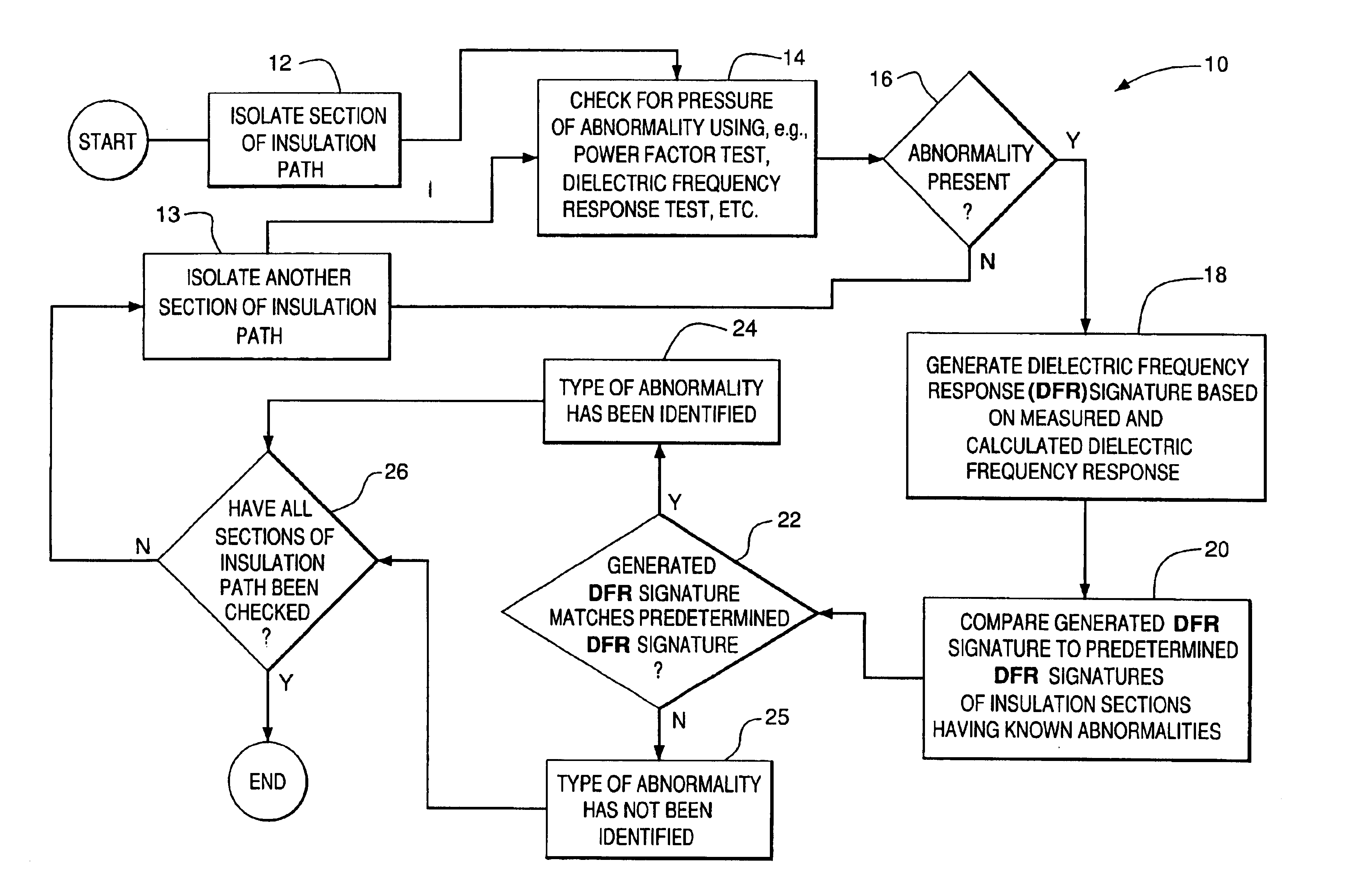
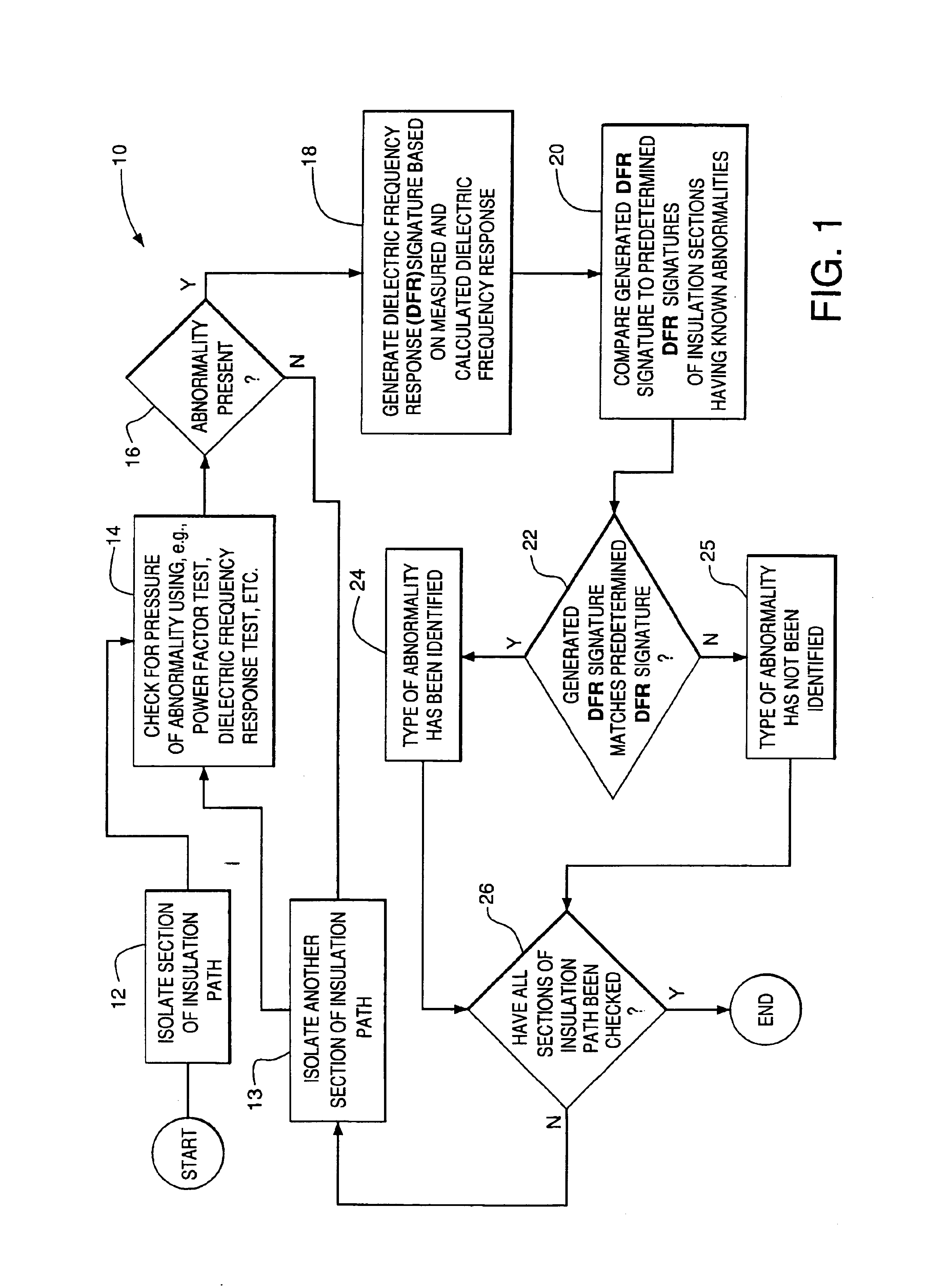
A preferred process 10 for identifying an abnormality, e.g., a defect, in an insulation system of an electrical-power transformer is depicted in FIG. 1. The process 10 is described in connection with a conventional power transformer 50 depicted, in part, in FIG. 2. Specific details relating to the power transformer 50 are presented for exemplary purposes only, as the process 10 can be used in conjunction with virtually any type of power transformer.

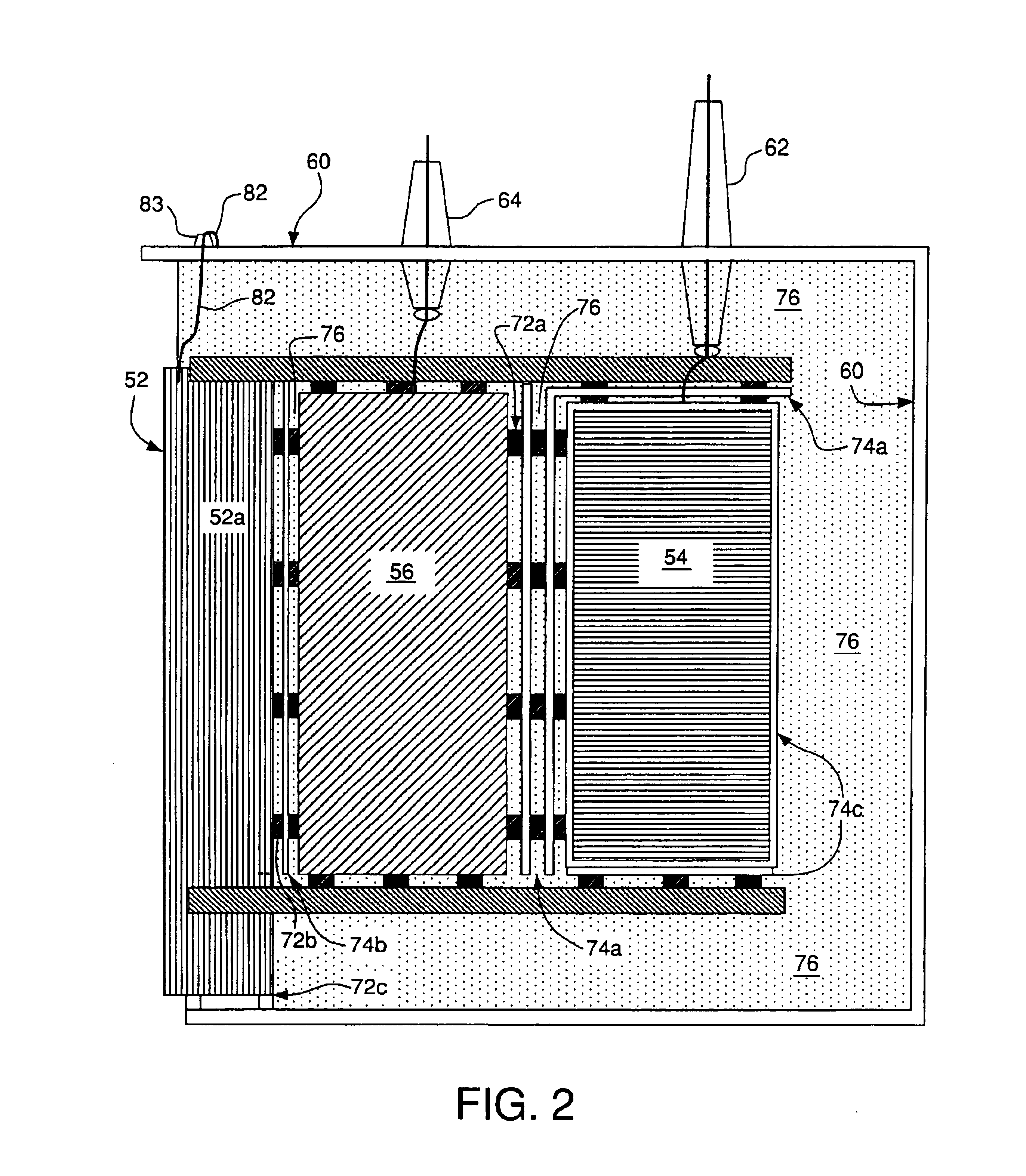
The power transformer 50 comprises a core 52 having a leg 52a (the core 52 also comprises other legs not visible in FIG. 1). The transformer 50 further comprises a low-voltage winding 56 positioned around the leg 52a, and a high-voltage winding 54 positioned around the low-voltage winding 56. The core 52, high-voltage winding 54, and low-voltage winding 56 are housed in a casing 60. It should be noted that the transformer 50 is depicted diagrammatically in FIG. 1. Various components of the transformer 50 are not shown in FIG. 1, and the s...


PUM


Abstract

A preferred method for identifying a type of abnormality in an insulation system of a power transformer comprises measuring dielectric losses in a section of the insulation system, calculating theoretical dielectric losses for the section based on the material properties, geometry, and temperature of the section, and generating a graphical representation of a percent difference between the measured and calculated dielectric losses. The preferred method also comprises comparing a shape of the graphical representation with a shape of one or more graphical representations of a percent difference between measured and theoretical dielectric losses in one or more other sections of insulation each known to have a specific type of abnormality.

Description

FIELD OF THE INVENTIONThe present invention relates to power transformers and, more particularly, to a method for identifying abnormalities in power transformers.BACKGROUND OF THE INVENTIONPower transformers typically include insulation positioned between or around the various conductive paths therein. The insulation is often formed from a paper or cellulose material. Mineral oil is also commonly used as an insulator in power transformers.Defects or other abnormalities in the insulation of a power transformer can substantially degrade the performance of the power transformer and, in extreme cases, can cause potentially dangerous malfunctions. For example, moisture and contaminates can degrade the insulating properties of oil, paper, and cellulose insulators. The properties of an insulator can also degrade if the insulator is exposed to voltages greater than its rated voltage. Moreover, defects such as tears, voids, and other flaws, as well as excessive moisture and carbon tracking, ...

Claims


Application Information

Patent Timeline
IPC IPC(8): G01R31/06G01R31/12G01R31/02G01R27/26
CPCG01R31/1263G01R31/027G01R31/025G01R27/2688G01R31/52G01R31/62
Inventor PERKINS, MARK D.FAZLAGIC, ASIM
Owner HITACHI ENERGY SWITZERLAND AG
Learn More