

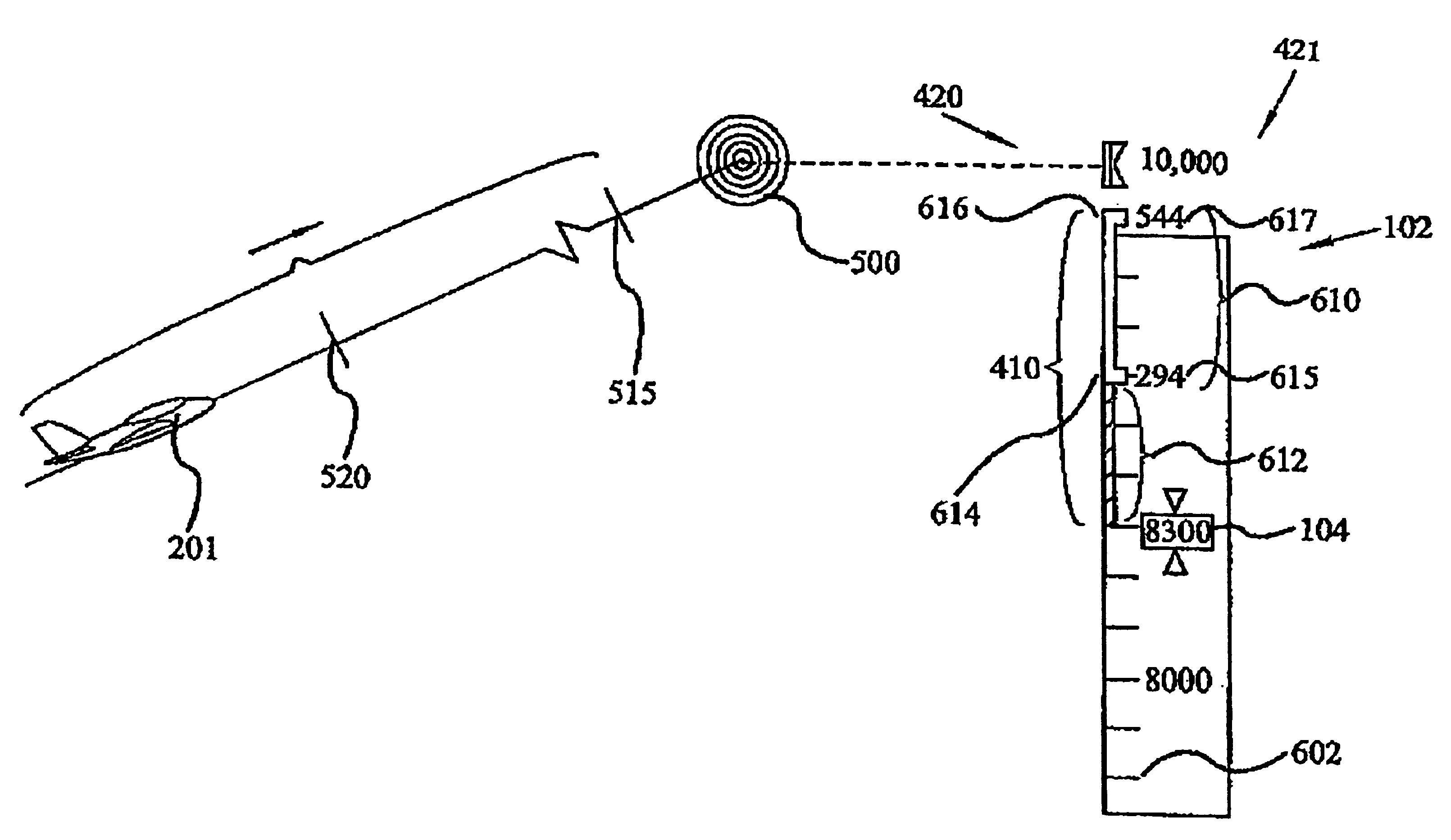
Display of altitude and path capture trajectories
a technology of path capture and display, applied in the field of aircraft flight instrument systems, can solve the problems of difficult to perform the same task under manual control, inconvenient operation, and inability to display information
- Summary
- Abstract
- Description
- Claims
- Application Information
AI Technical Summary
Benefits of technology
Problems solved by technology
Method used
Image

Examples
Embodiment Construction
Various aspects of the present invention may be described herein in terms of functional block components and various processing steps. It should be appreciated that such functional blocks may be realized by any number of hardware and / or software components or computer systems configured to perform the specified functions. For example, one or more components may employ various computer systems, e.g., microprocessor or micro controller—based systems, and the like, which may carry out a variety of functions under the control of one or more microprocessors or other control devices. Similarly, the software elements of the present invention may be implemented with any programming or scripting languages such as C, C++, Java, Assembly Language, PERL, or the like, or any combination thereof, with the various algorithms being implemented with any combination of data structures, objects, processes, routines or other programming elements. Further, it should be noted that various elements may em...
PUM
 Abstract
Description
Claims
Application Information