Beam-forming antenna system

a beam-forming antenna and beam-forming technology, applied in the field of antennas, can solve the problems of difficult and expensive manufacturing of structures, high-frequency antennas that are often cumbersome to manufacture, and require expensive micro-machining and hand-tuning

Inactive Publication Date: 2005-03-22
MOHAMADI FARROKH
View PDF22 Cites 99 Cited by
  • Summary
  • Abstract
  • Description
  • Claims
  • Application Information

AI Technical Summary

Problems solved by technology

Conventional high-frequency antennas are often cumbersome to manufacture.
For example, antennas designed for 100 GHz bandwidths typically use machined waveguides as feed structures, requiring expensive micro-machining and hand-tuning.
Not only are these structures difficult and expensive to manufacture, they are also incompatible with integration to standard semiconductor processes.
As is the case with individual conventional high-frequency antennas, beam-forming arrays of such antennas are also generally difficult and expensive to manufacture.
Conventional beam-forming arrays require complicated feed structures and phase-shifters that are incompatible with a semiconductor-based design.
In addition, conventional beam-forming arrays become incompatible with digital signal processing techniques as the operating frequency is increased.
For example, at the higher data rates enabled by high frequency operation, multipath fading and cross-interference becomes a serious issue.

Method used


Image

  • Beam-forming antenna system
  • Beam-forming antenna system
  • Beam-forming antenna system

Examples


Embodiment Construction

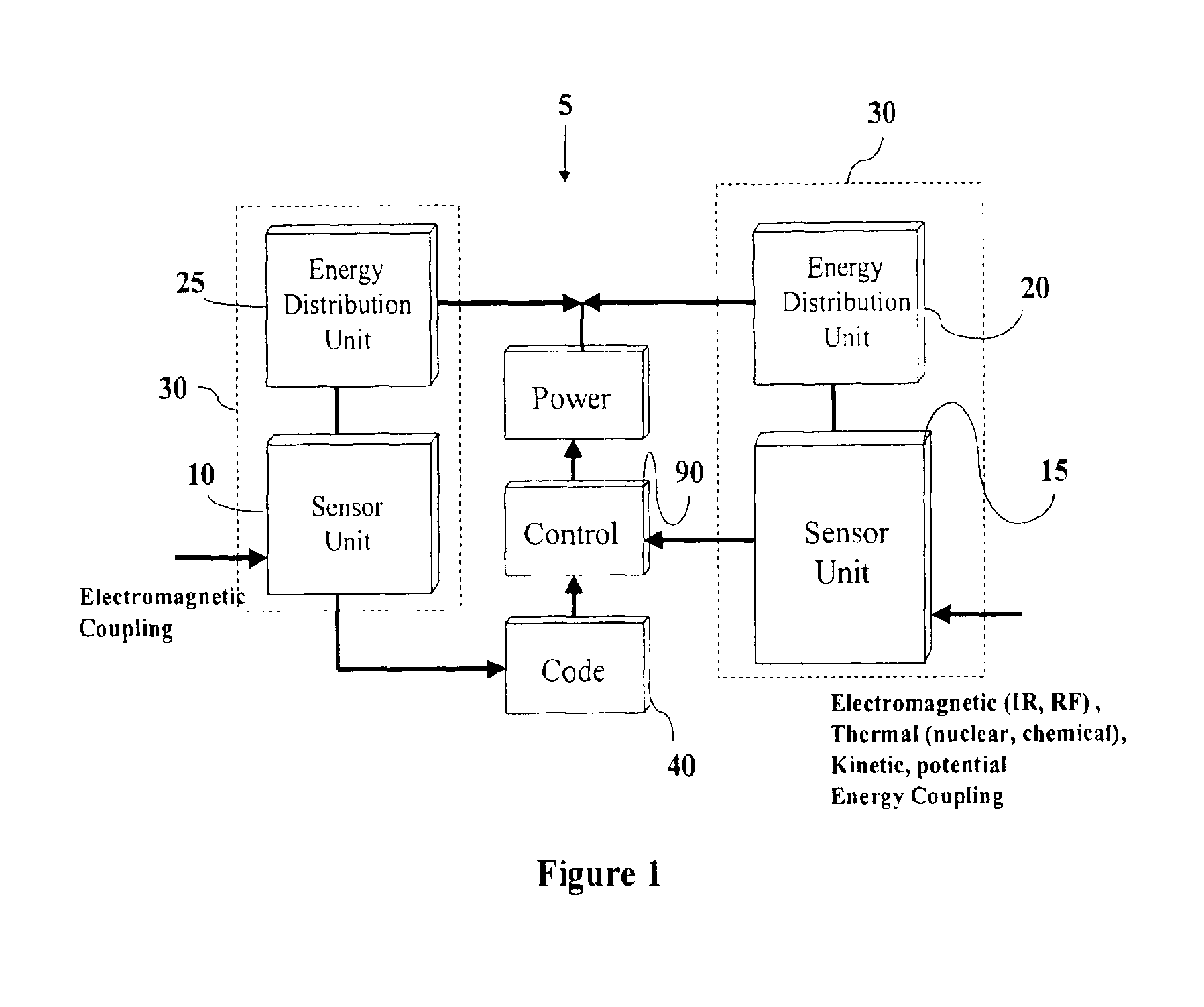
As seen in FIG. 1, a wireless remote sensor 5 includes an antenna or antenna array 10 that converts received RF energy into electrical current that is then coupled to energy distribution unit 20. Alternatively, other sources of energy besides RF energy may be converted to electrical charge by sensor unit 15 coupled to an energy distribution unit 20. For example, sensor unit 15 may sense and convert thermal energy (such as from a nuclear or chemical reaction), kinetic energy, pressure changes, light / photonics, or other suitable energy sources. Together, each sensor unit 10 or 15 and energy distribution unit 20 forms an energy conversion unit 30. To enable active rather than passive operation, wireless remote sensor 5 may also include a battery (not illustrated).

Code unit 40 responds to the stimulation of sensor unit 10 or 15 and provides the proper code to indicate the source of the stimulation. For example, should sensor 15 be a piezoelectric transducer, impact of an object on senso...


PUM


Abstract

A beam-forming antenna system includes an array of integrated antenna units. Each integrated antenna unit includes an oscillator coupled to an antenna. A network couples to the integrated antenna units to provide phasing information to the oscillators. A controller controls the phasing information provided by the network to the oscillators.

Description

TECHNICAL FIELDThe present invention relates generally to antennas, and more particularly to an antenna array compatible with standard semiconductor manufacturing techniques.BACKGROUNDConventional high-frequency antennas are often cumbersome to manufacture. For example, antennas designed for 100 GHz bandwidths typically use machined waveguides as feed structures, requiring expensive micro-machining and hand-tuning. Not only are these structures difficult and expensive to manufacture, they are also incompatible with integration to standard semiconductor processes.As is the case with individual conventional high-frequency antennas, beam-forming arrays of such antennas are also generally difficult and expensive to manufacture. Conventional beam-forming arrays require complicated feed structures and phase-shifters that are incompatible with a semiconductor-based design. In addition, conventional beam-forming arrays become incompatible with digital signal processing techniques as the ope...

Claims


Application Information

Patent Timeline
Patent Type & Authority Patents(United States)
IPC IPC(8): H01Q9/04H01Q9/28H01Q19/00H01Q3/26H01Q21/08H01Q1/36H01Q9/16
CPCH01Q1/36H01Q9/16H01Q9/0457H01Q3/2605
Inventor MOHAMADI, FARROKH
Owner MOHAMADI FARROKH
Why Eureka
Try Eureka