Electrolytic capacitor

a technology of electrolytic capacitors and capacitors, applied in the direction of fixed capacitor details, casings/cabinets/drawers, electrical equipment casings/cabinets/drawers, etc., can solve the problem of insufficient lowering of impedance, and achieve the effect of reducing esl more effectively

Active Publication Date: 2005-03-22
MURATA MFG CO LTD
View PDF17 Cites 79 Cited by
  • Summary
  • Abstract
  • Description
  • Claims
  • Application Information

AI Technical Summary

Benefits of technology

Preferably, the anode electrode pattern is formed with a plurality of first conductive paths, the cathode electrode pattern is formed with the same number of second conductive paths as that of the first conductive paths, and the first and second conductive paths corresponding to each other align with each other along a direction in which the anode and cathode electrode patterns align with each other. In this case, each pair of the first and second conductive paths corresponding to each other contribute to lowering the ESL, whereby the ESL can be reduced more effectively.
Preferably, each of the first and second conductive paths has a cross section extending in one direction, and the first and second conductive paths corresponding to each other extend in parallel. In this case, the first and second conductive paths contribute to lowering the ESL over a wide area, whereby the ESL can be reduced more effectively.
Preferably, in the anode electrode pattern and cathode protruded pattern part adjacent each other, marginal areas opposing each other are formed with a plurality of first conductive paths and a plurality of second conductive paths whose number is the same as that of the first conductive paths, and the first and second conductive paths corresponding to each other align with each other along a direction in which the anode electrode pattern and the cathode protruded pattern part align with each other. In this case, each pair of the first and second conductive paths aligning along a direction in which the anode electrode pattern and the cathode protruded pattern part align with each other contribute to lowering the ESL, whereby the ESL can be reduced more effectively.
Preferably, each of the first and second conductive paths has a cross section extending in one direction, and the first and second conductive paths corresponding to each other extend in parallel. In this case, the first and second conductive paths contribute to lowering the ESL over a wide area, whereby the ESL can be reduced more effectively.

Problems solved by technology

However, the following problem exists in the above-mentioned conventional electrolytic capacitor.
Therefore, the conventional electrolytic capacitor has been problematic in that the ESL caused by currents flowing through these through holes is so high that impedance is not lowered sufficiently.

Method used


Image

  • Electrolytic capacitor
  • Electrolytic capacitor
  • Electrolytic capacitor

Examples


example 1

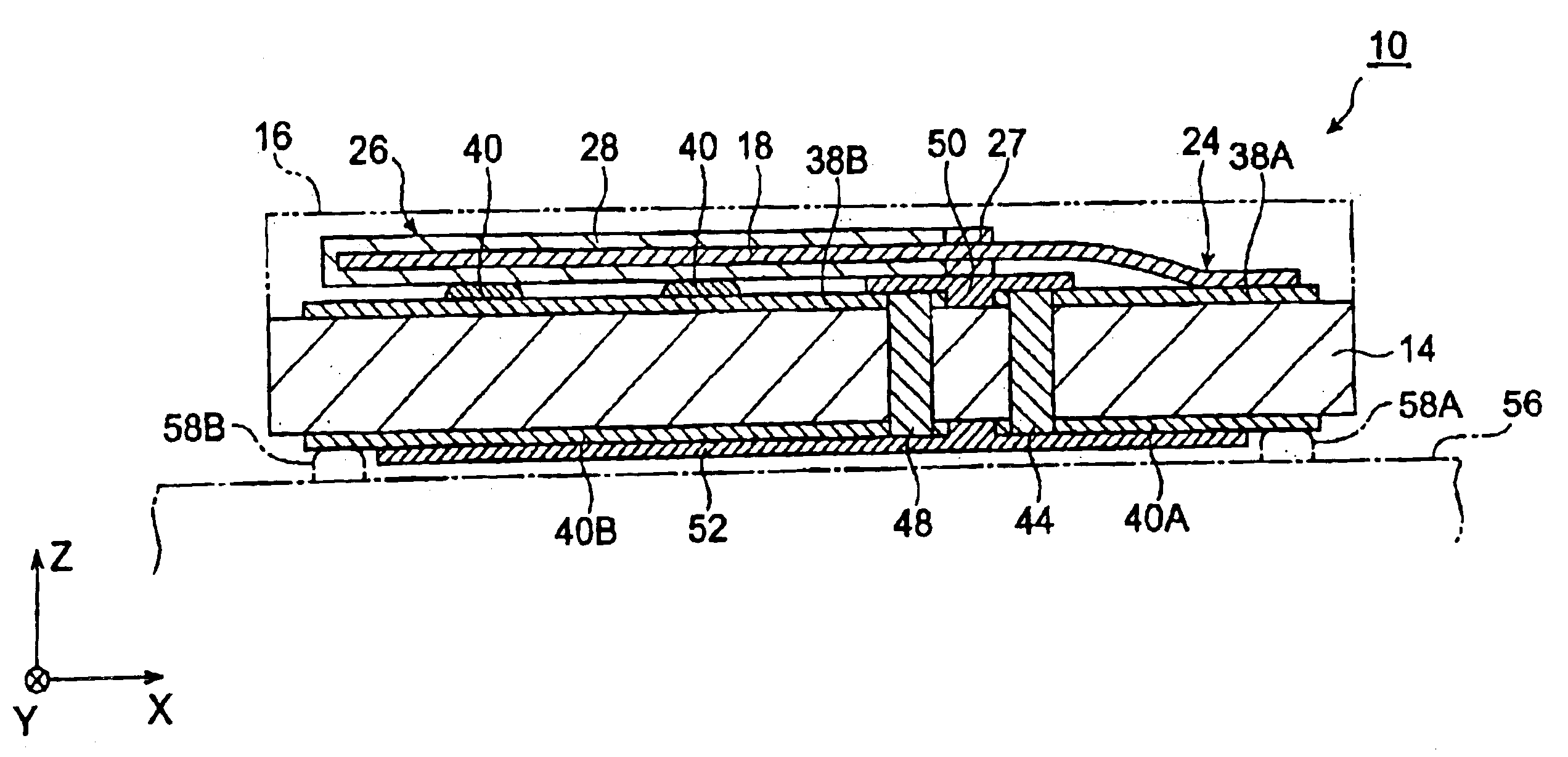
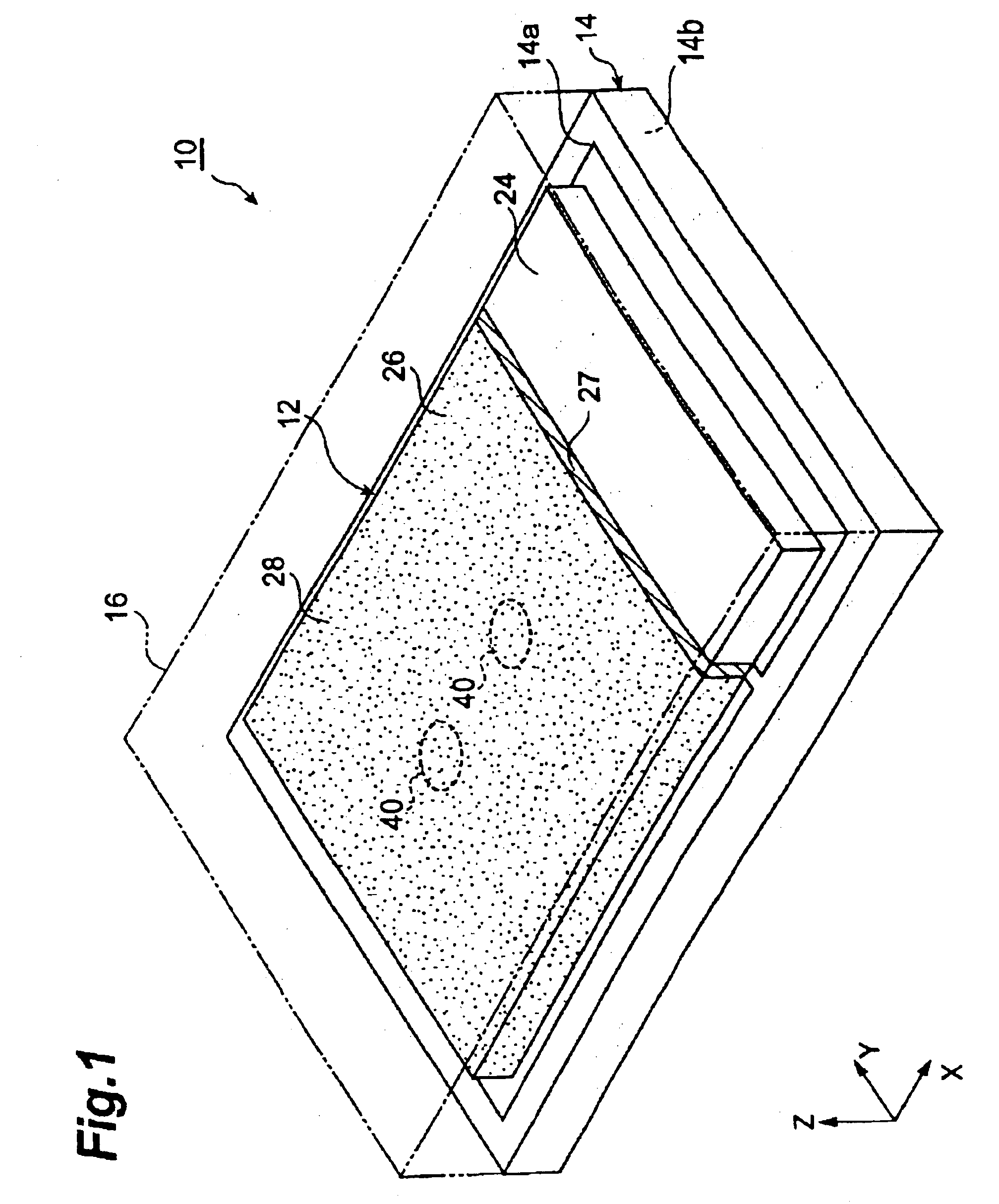
In the following manner, an electrolytic capacitor similar to the electrolytic capacitor 10 shown in FIG. 1 was produced.

First, from a roughened aluminum foil sheet, formed with an aluminum oxide film, having a thickness of 100 μm and yielding a capacitance of 270 μF / cm2, an aluminum anode electrode body was produced by punching so as to attain a form identical to that of the aluminum foil 30 shown in FIG. 3 with a size of 4.7 mm×3.5 mm (an area of 0.165 cm2) excluding the portion corresponding to the anode part. In thus punched electrode body, the roughened structure in the region (region corresponding to numeral 27 in FIG. 3) to be formed with an insulative resin layer was destroyed by pressing. In thus produced electrode body, only the surface of the pressed region (region corresponding to numeral 27 in FIG. 3) was coated with an epoxy resin.

Thus obtained electrode body was set in an aqueous ammonium adipate solution with a concentration of 3 wt % whose pH was adjusted to 6.0, su...

example 2

In the following manner, an electrolytic capacitor similar to the electrolytic capacitor shown in FIG. 7 was produced.

First, from a roughened aluminum foil sheet, formed with an aluminum oxide film, having a thickness of 100 μm and yielding a capacitance of 270 μF / cm2, an aluminum anode electrode body was produced by punching so as to attain a form identical to that of the aluminum foil 130 shown in FIG. 8 with a size of 6.5 mm×3.0 mm (an area of 0.195 cm2) excluding the four protruded parts (the parts referred to with numeral 124A). In thus punched electrode body, the roughened structure in the region (region corresponding to numeral 127 in FIG. 8) to be formed with an insulative resin layer was destroyed by pressing. In thus produced electrode body, only the surface of the pressed region (region corresponding to numeral 127 in FIG. 8) was coated with an epoxy resin.

Thereafter, only the protruded parts 124A on one side (two of the four anode parts) among the four protruded parts co...


PUM


Abstract

An electrolytic capacitor with a further lowered impedance is provided. In the electrolytic capacitor in accordance with the present invention, respective currents directed opposite from each other flow through anode and cathode vias extending along the thickness of a substrate. The anode vias are lopsidedly located in a marginal area of an anode electrode pattern, and thus are disposed significantly close to the cathode vias formed in a cathode electrode pattern disposed close to the anode electrode pattern. The cathode vias are lopsidedly located in a marginal area of the cathode electrode pattern, and thus are disposed significantly close to the anode vias. Since the anode and cathode vias are formed close to each other as such, this electrolytic capacitor achieves a lower ESL, thereby attaining an impedance lower than that of a conventional electrolytic capacitor.

Description

BACKGROUND OF THE INVENTION1. Field of the InventionThe present invention relates to an electrolytic capacitor.2. Related Background ArtIn general, a capacitor device employed in an electrolytic capacitor is made by using a metal (so-called valve metal) capable of forming an insulative oxidized film, such as aluminum, titanium, and tantalum, as an anode; forming an insulative oxidized film by anodizing the surface of the valve metal; then forming a solid electrolyte layer made of an organic compound or the like substantially functioning as a cathode; and further providing a conductive layer made of graphite, silver, or the like as a cathode.Known as methods for achieving a low impedance in such an electrolytic capacitor are those lowering equivalent series inductance (ESL) and equivalent series resistance (ESR). An electrolytic capacitor omitting a lead frame for lowering ESR is disclosed in Japanese Patent Application Laid-Open No. 2001-102252. The electrolytic capacitor disclosed ...

Claims


Application Information

Patent Timeline
Patent Type & Authority Patents(United States)
IPC IPC(8): H01G9/04H01G9/004H01G9/10H01G9/14H01G9/012H01G9/045H01G9/15
CPCH01G9/012H01G9/15H01G9/045
Inventor BURKET, CHRIS T.YOSHIHARA, YUMIKOKOBAYASHI, MASAAKI
Owner MURATA MFG CO LTD
Why Eureka
Try Eureka