
Dipole radiating dynamic speaker

a dynamic speaker and dipole technology, applied in the field of dynamic speakers, can solve the problem that dipole radiating speakers were only available, and achieve the effect of improving the audio reproduction quality of dynamic speakers

Inactive Publication Date: 2005-03-22
MARNIE GLENN A
View PDF12 Cites 6 Cited by
  • Summary
  • Abstract
  • Description
  • Claims
  • Application Information

AI Technical Summary

Benefits of technology

Accordingly, it is the primary object of this invention to improve the audio reproduction quality of dynamic speakers used in home, automotive, and professional applications. It is another principal object of the present invention to provide a dynamic speaker design utilizing a diaphragm, voice coil assembly, and magnet system that produces acoustic output as a dipole radiator. It is a further object of the present invention to provide a method of utilizing the dipole radiating dynamic speaker design for tweeter and mid-range speaker applications used in home, automotive, and professional audio systems.
The present invention provides a significant advance in the art by providing a dynamic speaker that produces acoustic output as a dipole radiator. In contrast to prior art dynamic speaker design, the dipole radiator produces acoustic output of equal magnitude in the forward and rearward directions permitting the diaphragm to move only in response to the electrical input signal. In accordance with the present invention a venting means is provided to permit the rearward acoustic output to propagate away from the diaphragm, thus minimizing or eliminating the adverse effects that cause audio reproduction quality degradation. The dipole radiating dynamic speaker design disclosed herein utilizes vents that provide minimal obstruction to the rearward acoustic output propagation and thus in effect produces acoustic output as a dipole radiator.
The invention further provides a point source acoustic dipole output that produces superior imaging resolution, and improved audio reproduction accuracy compared to the prior art speaker design. The invention further provides an inexpensive means to manufacture a dipole radiating speaker with conventional dynamic speaker manufacturing techniques, equipment, and components. Previously dipole radiating speakers were only available in other more expensive speaker design technologies such as electrostatic, planar magnetic, and ribbon type.
The invention further provides a method of utilizing the dipole radiating dynamic speaker without the need for an enclosure by mounting the speaker on a panel device that permits the rearward acoustic output to propagate away from the diaphragm. The invention further provides a method of utilizing the dipole radiating dynamic speaker for mid-range applications with a front panel perimeter vented enclosure design that permits a portion of the acoustic output to directly exit the enclosure providing improved audio reproduction quality compared to prior art enclosure designs.
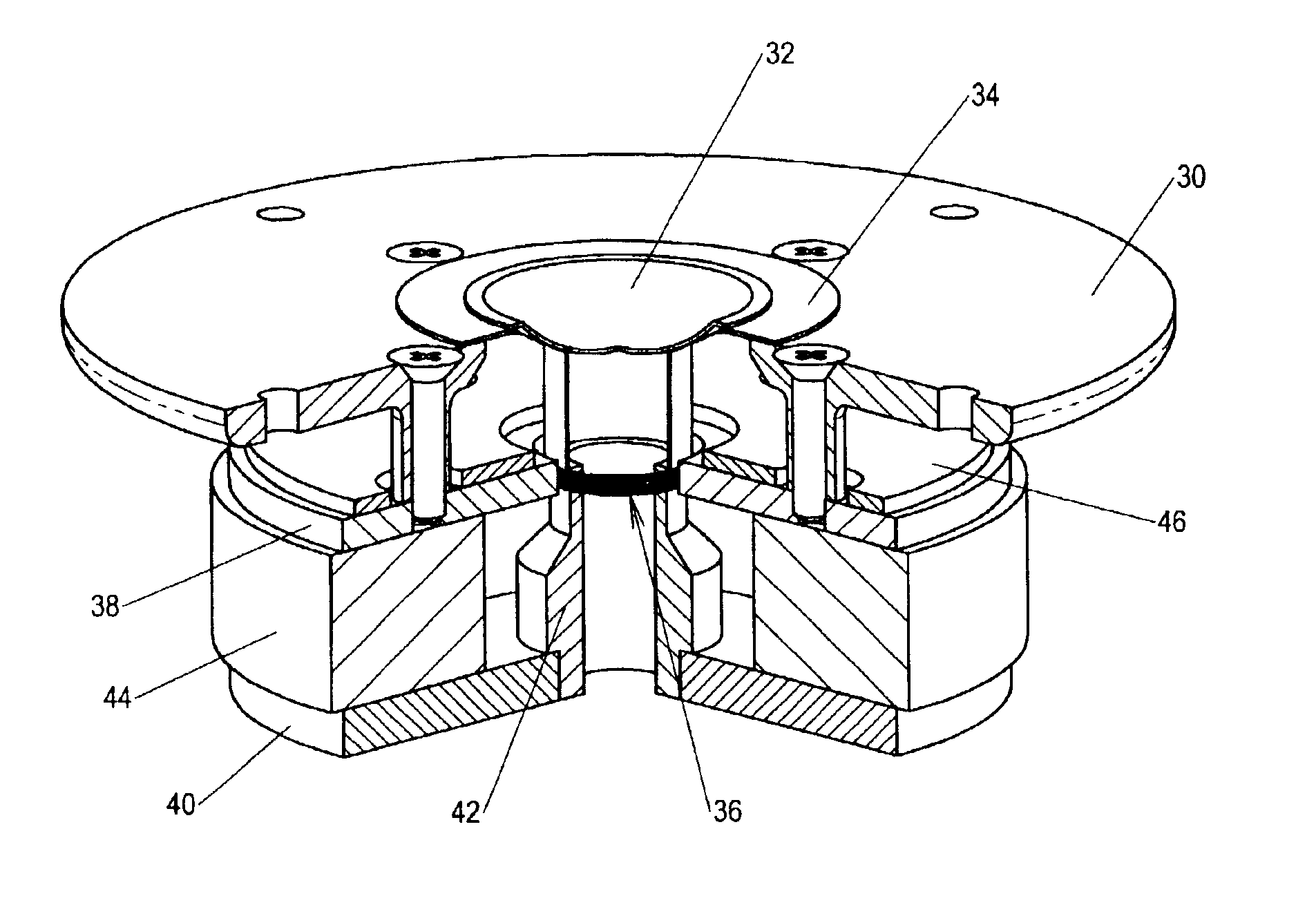
The dipole radiating dynamic speaker functions under the same electro-dynamic principles as conventional dynamic speakers. In operation, the diaphragm vibrates proportional to the electrical signal passing through the voice coil producing forward and rearward propagating acoustic output. The dipole radiating dynamic speaker construction utilizes a vented pole flux conductor that provides a passage for the rearward acoustic output that is generated by the diaphragm contained within the perimeter of the voice coil assembly. The vent located between the frame and the front flux conductor plate provides a passage of minimal obstruction for the rearward acoustic output that is generated by the diaphragm adjacent to the voice coil assembly. FIG. 7 illustrates the acoustic output passages provided by a typical dipole radiating dynamic speaker. It is readily apparent that the rearward propagating acoustic output travels away from the diaphragm thus minimizing or eliminating the adverse effects that cause sound quality degradation. By permitting the rearward propagating acoustic output to exit the rear of the speaker with minimal obstruction the diaphragm moves only in proportion to the electrical input signal and is not negatively impacted by trapped acoustic output. The speaker may additionally contain acoustic damping material to cover reflective surfaces to reduce acoustic reflections internal to the speaker.

Problems solved by technology

Previously dipole radiating speakers were only available in other more expensive speaker design technologies such as electrostatic, planar magnetic, and ribbon type.

Method used


Image

  • Dipole radiating dynamic speaker
  • Dipole radiating dynamic speaker
  • Dipole radiating dynamic speaker

Examples


Embodiment Construction

Referring to FIG. 3, in accordance with the present invention the dipole radiating dynamic speaker broadly comprises a frame 30, diaphragm 32, suspension 34, voice coil assembly 36, front flux conductor plate 38, rear flux conductor plate 40, vented pole flux conductor 42, permanent magnet 44, and acoustic damping material 46.

The frame 30 contains a centrally located aperture for the purpose of supporting the diaphragm 32. In accordance with the present invention, the frame 30 comprises a plurality of integral standoff posts located on the rear surface that provide a vent between the frame 30 and the front flux conductor plate 38. This vent provides a passage of minimal obstruction for the rearward acoustic output to propagate away from the diaphragm 32.

The diaphragm 32 is preferably an inverted dome shape and composed of a suitably light weight rigid material. The diaphragm 32 perimeter is preferably attached with an adhesive to a suspension 34 that suspends the diaphragm within th...


PUM


Abstract

A dipole radiating dynamic speaker design comprises a diaphragm (32) providing a surface for radiating acoustic output, a voice coil assembly (36) for driving the diaphragm, and a magnet system for providing magnetic flux across the voice coil assembly. The speaker incorporates a vented pole flux conductor (42) and a vent adjacent to the diaphragm permitting the rearward acoustic output to propagate away from the diaphragm producing acoustic output as a dipole radiator.A method of utilizing the dipole radiating dynamic speaker design for tweeter and mid-range speaker applications used in home, automotive, and professional audio systems is disclosed. In addition a novel enclosure design is disclosed that utilizes a front panel perimeter vent providing improvement of audio reproduction quality for mid-range speaker applications.

Description

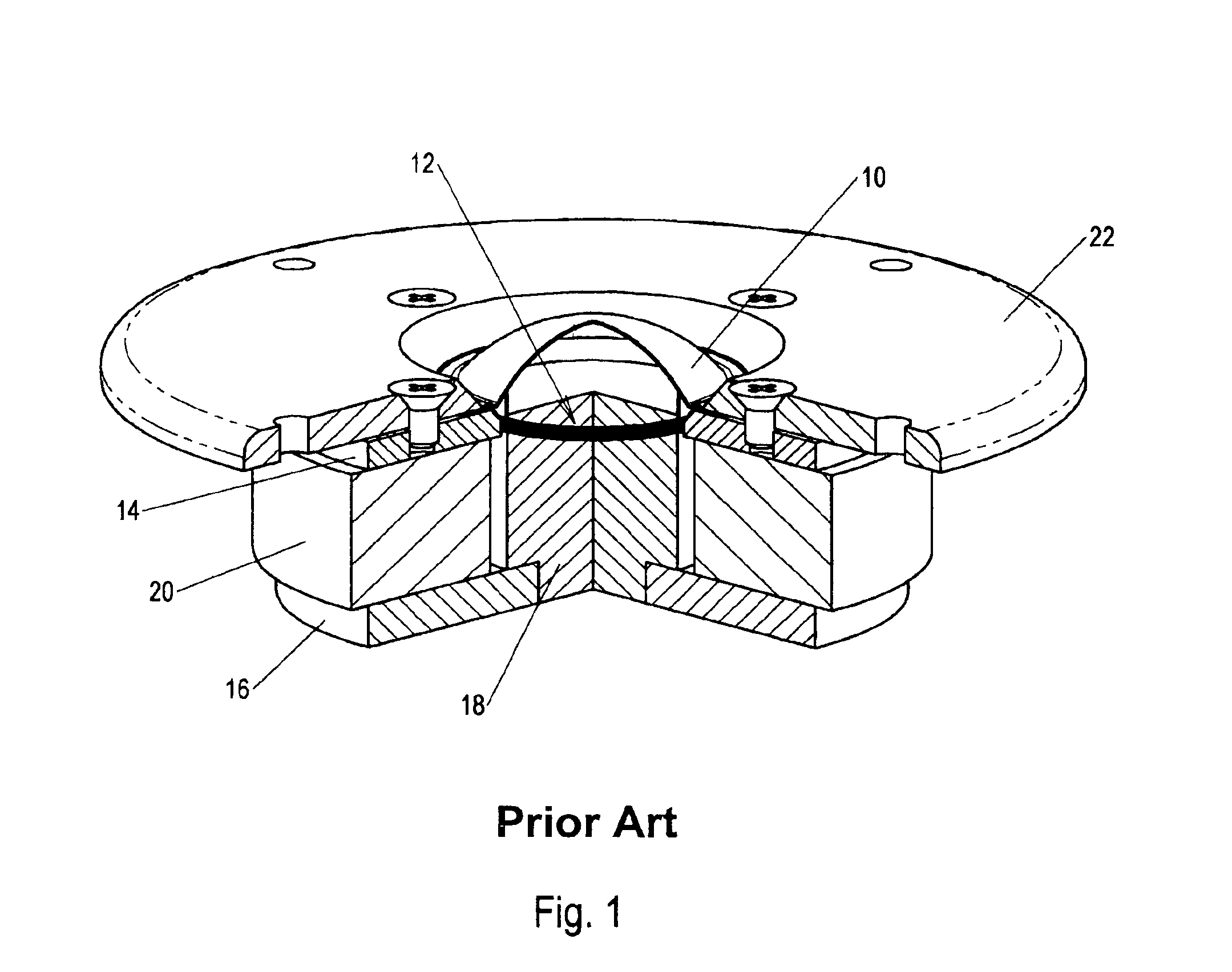
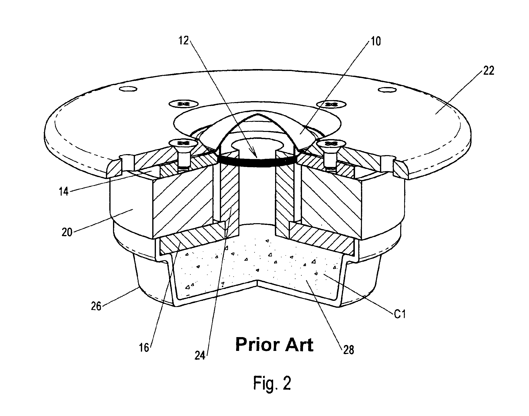
BACKGROUND OF THE INVENTIONThis invention relates to a dynamic speaker design utilizing a diaphragm, voice coil assembly, and magnet system producing acoustic output as a dipole radiator. The invention also relates to a method of utilizing the dipole radiating dynamic speaker design for tweeter and mid-range speaker applications used in home, automotive, and professional audio systems.Dynamic speakers utilizing a diaphragm, voice coil assembly, and magnet system providing acoustic output as monopole radiators have been manufactured for many years and are still widely used in commercial, professional, and home applications. The dynamic speaker has endured as the most popular speaker design due to its low cost, compact design, ease of use, and reliability. However, the dynamic monopole speaker audio reproduction quality is considered inferior to other more expensive speaker design technologies such as electrostatic, planar magnetic, and ribbon type.A dynamic speaker system generally u...

Claims


Application Information

Patent Timeline
IPC IPC(8): H04R9/00H04R9/06H04R1/20
CPCH04R9/06H04R1/20
Inventor MARNIE, GLENN A.
Owner MARNIE GLENN A
Learn More