Two-stage optical isolator with simplified assembly process and improved performance

Inactive Publication Date: 2005-03-22
KONCENT COMM +1
View PDF1 Cites 0 Cited by
  • Summary
  • Abstract
  • Description
  • Claims
  • Application Information

AI Technical Summary

Benefits of technology

[0005]It is therefore an object of the present invention to provide new isolator configuration and methods of manufacture for producing isolator with less number of required optical wedges. The isolator can be produced at lower cost with simpler assembling process and achieving better performance with reduced polarization dependent losses thus resolving the difficulties and limitations discussed above.
[0006]Specifically, it is an object of the present invention to provide a new isolator configuration by using three birefringent optical wedges thus reduces the number of components required to produce isolator using a simplified manufacturing process and providing higher reliable isolators. Furthermore, the isolator has less insertion loss and polarization dependent loss (PDL) because the optical transmission is projected through less number of interfacing surfaces in the isolator of this invention then that of the conventional isolators.

Problems solved by technology

As a result, the conventional isolators are more difficult to assemble due to the fact that there are more interfacing surfaces between these four wedges, and that the relative orientations of the optical axes among these wedges have to be precisely aligned to guarantee good isolation within certain bandwidth.
The reliability is often degraded due to the difficulties in the assembling processes.
All these difficulties limit the usefulness and functionality of the conventional isolators.

Method used


Image

  • Two-stage optical isolator with simplified assembly process and improved performance
  • Two-stage optical isolator with simplified assembly process and improved performance
  • Two-stage optical isolator with simplified assembly process and improved performance

Examples


Embodiment Construction

ission of an isolator of this invention; and

[0011]FIG. 3 is a cross sectional view of a preferred embodiment of an isolator assembled according to the improved configuration of this invention.

DETAILED DESCRIPTION OF THE INVENTION

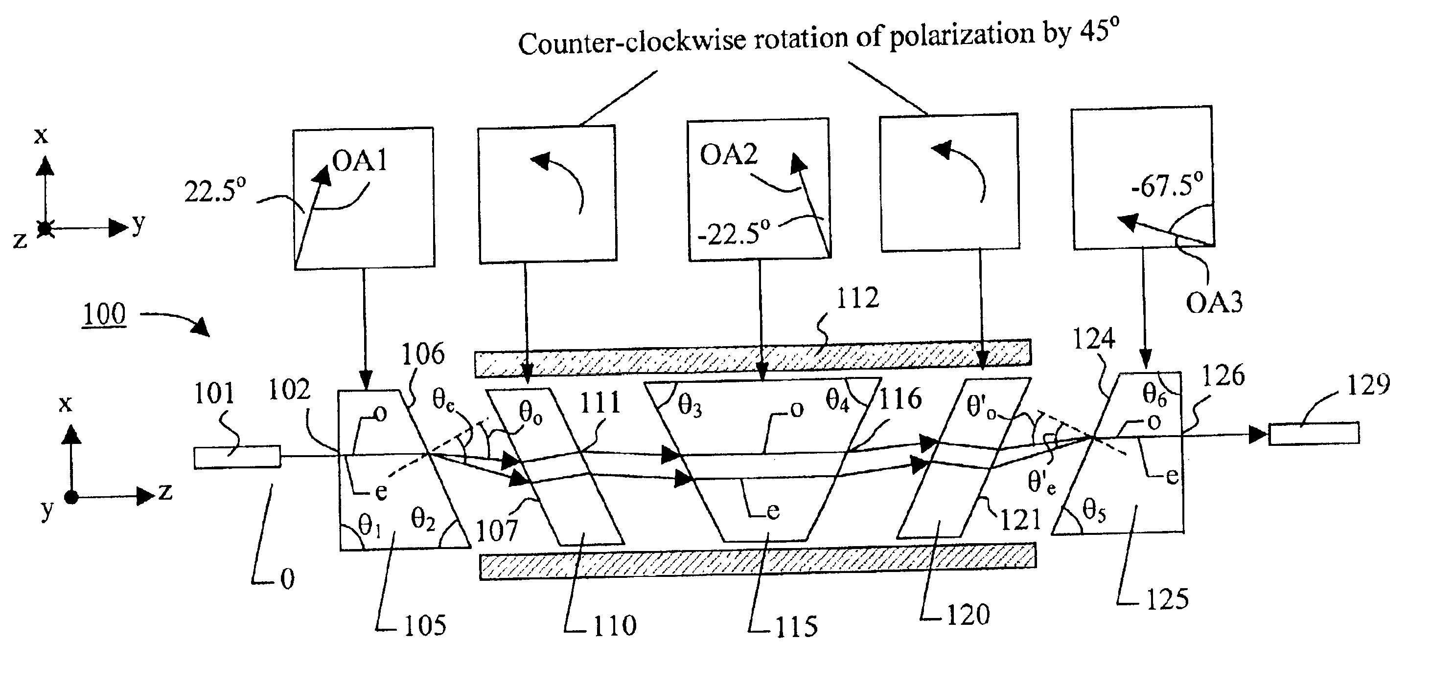
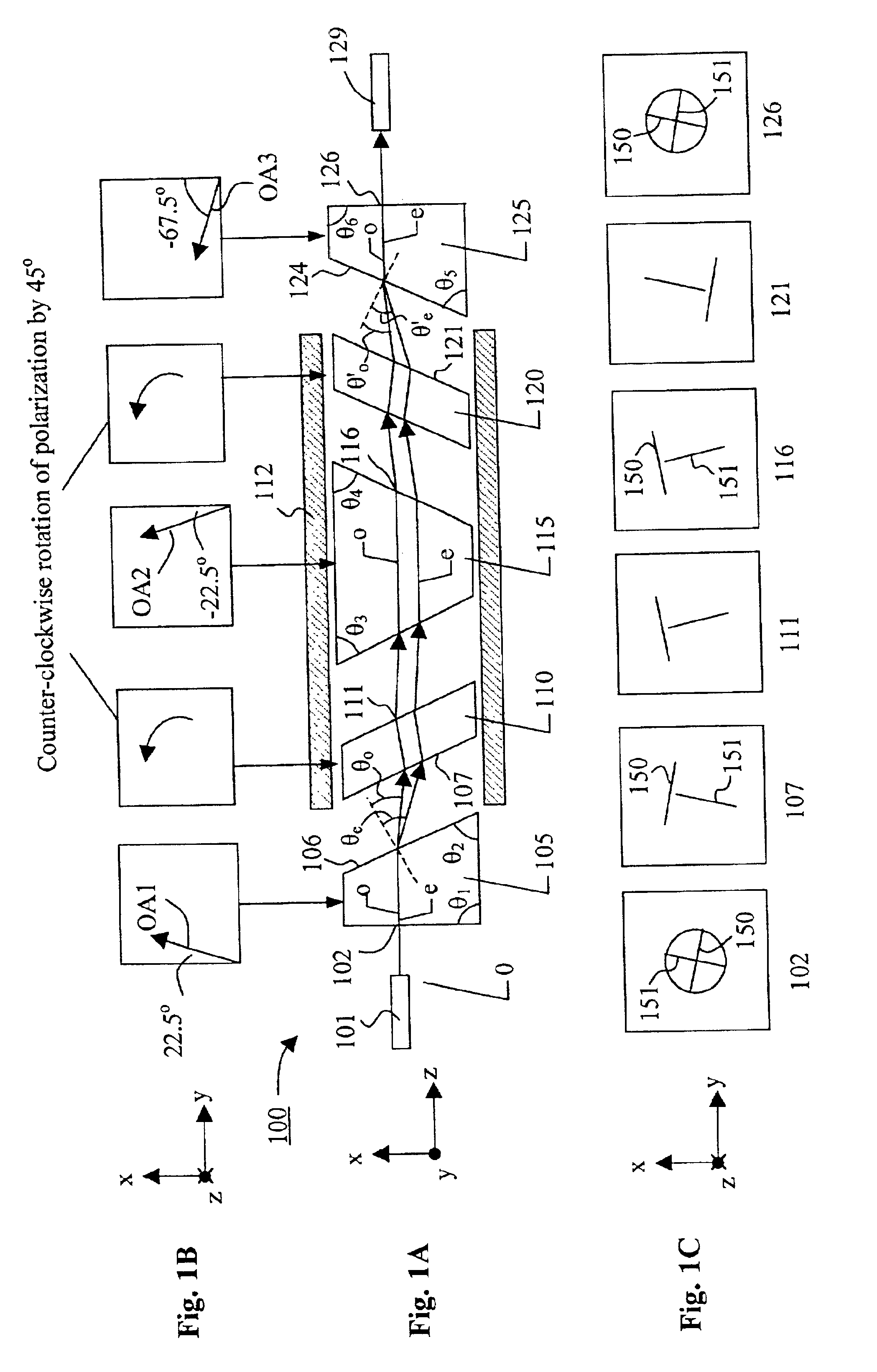
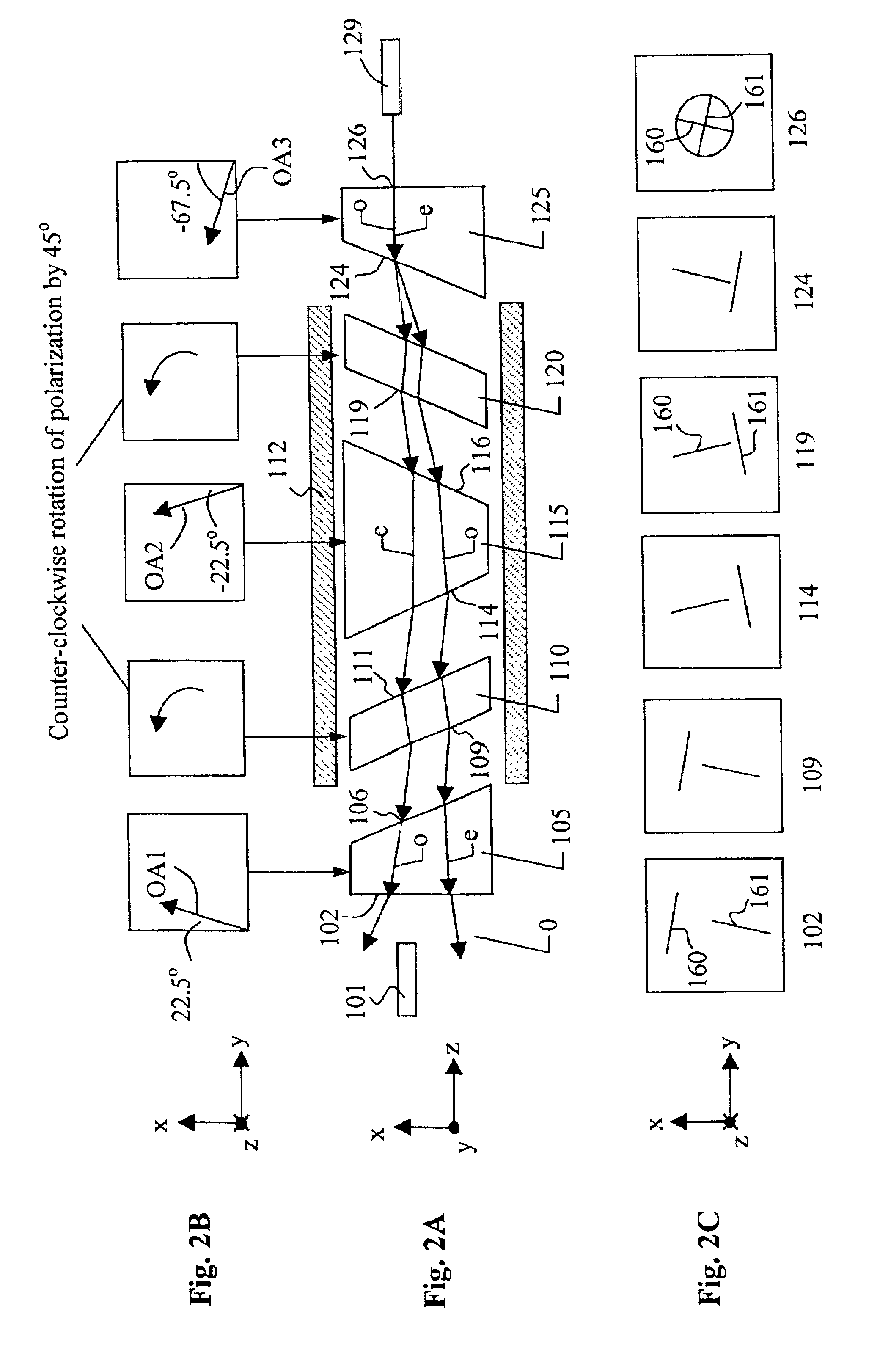
[0012]Referring to FIG. 1A for a side cross sectional view for showing the optical components of an isolator 100 of this invention. The isolator generally comprises first, second, and third birefringent elements 105, 115, and 125, first and second non-reciprocal polarization rotators 110, 120, and a permanent magnet ring 112. Associated with each of the optical components, FIG. 1B is a functional block diagram for showing the optical axis for each of the birefringent components and the direction of polarization rotation for each of the non-reciprocal polarization rotators. FIG. 1C is a polarization diagram for illustrating the position of the optical beams and state of polarization (SOP) on each of the interfacing surfaces immediately after the optical beams...


PUM


Abstract

The present invention discloses an optical isolator for preventing a reverse light transmission in a forward light transmission device. The optical isolator includes at least two birefringent crystals for forward projecting an incident light. The first birefringent crystal first separates the incident light into divergent beam components and the second birefringent crystal converges the divergent beam components into converging beam components for recombining into an output light. The second birefringent crystal receiving a light transmitting in a direction opposite the forward projecting incident light for producing separate and diverging beam components to project into the first birefringent crystal for further diverging the beam components by the first birefringent crystal.

Description

FIELD OF THE INVENTION[0002]This invention generally relates to devices implemented in optical communication systems. More specifically, this invention relates to optical isolator with improved performance of broad bandwidth and lower insertion while can be produced at lower cost with reduced size.BACKGROUND OF THE INVENTION[0003]Conventional two-stage isolators generally comprise two single-stage isolators in series to increase isolation and bandwidth. Each single-stage isolator further comprises one non-reciprocal polarization rotator and two birefringent optical wedges. Thus a total of four birefringent optical wedges are needed. As a result, the conventional isolators are more difficult to assemble due to the fact that there are more interfacing surfaces between these four wedges, and that the relative orientations of the optical axes among these wedges have to be precisely aligned to guarantee good isolation within certain bandwidth. In addition to the requirement of achieving ...

Claims


Application Information

Patent Timeline
IPC IPC(8): G02B6/26
CPCG02B6/2746
Inventor LIN, BINLIN, JINXIU
Owner KONCENT COMM
Why Eureka
Try Eureka