Method and apparatus for pore pressure monitoring

a technology of pore pressure and monitoring method, which is applied in the direction of survey, earthwork drilling and mining, and well accessories, etc., can solve the problems of unsatisfactory testing time, hazardous kick or circulation loss, and insufficient accurate knowledge of formation pressur

Inactive Publication Date: 2005-03-29
SCHLUMBERGER TECH CORP
View PDF15 Cites 11 Cited by
  • Summary
  • Abstract
  • Description
  • Claims
  • Application Information

AI Technical Summary

Benefits of technology

An advantage of this embodiment is that formation pore pressure information at the drill bit can be made available to the driller essentially in real time. The driller can then take appropriate and early action if e.g. there is an indication of a sharp increase in pore pressure.
It is desirable that the downhole container is mounted on a drill string adjacent the drill bit. When the formation sample comprises drill cuttings, this arrangement minimizes the exposure of the drill cuttings to drilling mud before they enter the container (so that, at least for low permeability formations, the initial pore pressure of the formation sample is substantially identical to the formation pore pressure immediately ahead of the drill bit). Also, when the sampled fluid is drilling mud, the baseline pressure is then substantially identical to the bottom hole mud pressure at the drill bit.
This embodiment of the method has an advantage over conventional wireline techniques for estimating formation pore pressure because of its suitability for analysing low permeability rocks. In particular, the relatively high surface area to volume ratio of the detached formation sample increases the rate of pressure equalization in the chamber compared to conventional techniques where a measuring tool is merely moved into engagement with the bulk formation at the wall of the wellbore.

Problems solved by technology

Determination of formation pressure while drilling has been a challenge to the oil and gas industry.
In many cases, however, accurate knowledge of the formation pressure is not so important as knowing whether it is above or below the downhole mud pressure.
If the mud pressure is not adjusted in time, such a differential can lead to a potentially hazardous kick or a circulation loss when the wellbore is extended to traverse the cover rock and re-enter high permeability formation.
However, because of the common practice of drilling overbalance, the pore pressure near the wellbore tends to be higher than the formation pore pressure at a distance from the wellbore.
Unfortunately, for low permeability formations, which take significant times to recover, the testing time then becomes unacceptably long.
For new wells in new formations, these methods do not provide reliable predictions of the formation pore pressure.

Method used


Image

  • Method and apparatus for pore pressure monitoring
  • Method and apparatus for pore pressure monitoring
  • Method and apparatus for pore pressure monitoring

Examples


Embodiment Construction

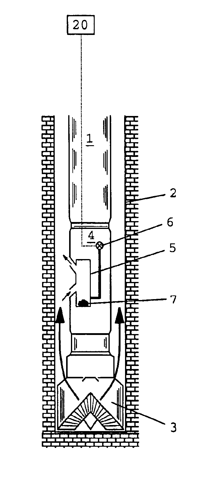
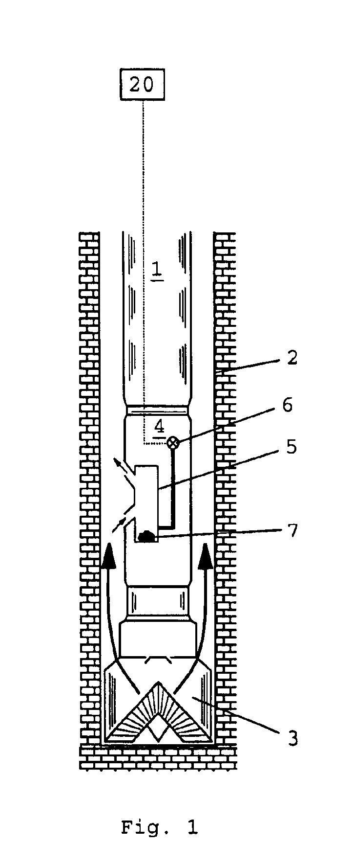
A major difficulty associated with the performance of pore pressure measurements on ultra low permeability rock formations concerns the very slow flow of fluid through such formations. This can lead to unacceptably long conventional testing times when direct pore pressure measurements are made on the bulk formation at the wall of the wellbore.

However, pore pressure monitoring according to the method of the present invention can operate on significantly shorter time scales because the pressure measurements can be made on formation samples with relatively high surface area to volume ratios which respond more quickly to changes in external pressure.

In practice, the sample (or components of the sample, if the sample comprises fragments or particles) should preferably be at or close to an optimal size which is large enough substantially to preserve the initial pore pressure during the period between collection of the sample and sealing in the container (when the sample may be exposed to ...


PUM


Abstract

A method of monitoring pore pressure, comprises the steps of:(a) providing downhole in a well a sealable container,(b) sealing in the container a sample of fluid at a baseline pressure and a sample of a formation having an initial pore pressure,(c) measuring the change in pressure of the fluid sample, the pressure of the fluid sample and the pore pressure of the formation sample sealed in the container tending to equalize over time, and(d) estimating the initial pore pressure relative to the baseline pressure from the measured change in fluid sample pressure.

Description

FIELD OF THE INVENTIONThe present invention relates to a method and an apparatus for monitoring pore pressures, and in particular for monitoring rock formation pore pressures in hydrocarbon wells.BACKGROUND TO THE INVENTIONDetermination of formation pressure while drilling has been a challenge to the oil and gas industry. Knowledge of formation pore pressure variation ahead of the drill bit would allow a driller to control the mud weight and the overbalance pressure (i.e. the difference between the bottom hole mud pressure and the formation pore pressure) in an optimal way, reducing permeability damage without compromising the safety of drilling operations.In many cases, however, accurate knowledge of the formation pressure is not so important as knowing whether it is above or below the downhole mud pressure. This information becomes crucially important when drilling through cover rock with very low permeability (e.g. shale or clay) separating high permeability formations, as the lo...

Claims


Application Information

Patent Timeline
Patent Type & Authority Patents(United States)
IPC IPC(8): E21B49/00E21B47/06
CPCE21B49/005E21B47/06
Inventor ZAZOVSKY, ALEXANDER
Owner SCHLUMBERGER TECH CORP
Why Eureka
Try Eureka