Pontoon with shell therefor

Inactive Publication Date: 2005-03-29
TREPANIER PAUL
View PDF18 Cites 12 Cited by
  • Summary
  • Abstract
  • Description
  • Claims
  • Application Information

AI Technical Summary

Benefits of technology

It is designed to be attachable to floating structures such as docks, pontoon boats and the like without requiring special tooling or manual dexterity through a set of quick, easy and ergonomic steps. Also, the proposed pontoon is adapted to provide long-time durability and ease of maintenance while being relatively easy to repair if damaged.
Furthermore, the proposed structure is designed so as to be relatively easily transported either to a launching site or in and out of the water once at the launching site. More specifically, the proposed pontoon is designed so as to reduce friction with a solid ground surface when the pontoon is being dragged into or out of a body of water.
Furthermore, the proposed pontoon is designed so as to be easily customizable with regards to the required positive buoyancy provided thereby. Optionally, the proposed pontoon may also be provided w

Problems solved by technology

While the use of such barrels typically made out of steel or the like has been a useful expedient, this practice nevertheless suffers from numerous drawbacks.
Docks and other floating structures made with steel barrels are relatively heavy and quite difficult to put in and take out, of the water.
Also, the steel of the barrels tends to rust and specially designed brackets are often needed to secure the barrels to the framework of the dock or raft.
Furthermore, the type of framework required with barrels is typically of a sizeable and expensive nature.
Although somewhat useful and providing for the recycling of used tires, they also suffer from numerous drawbacks, including the fact that they are relatively heavy.
They are also considered to be expensive relative to the amount of floatation capacity they provide.
Rigid foam made out of expanded polystyrene or the like have also been used with limited success since the latter has a tendency to deteriorate over time and to flake off or break up into small particles.
They further have a tendency to absorb water.
Although most conventional prior art pontoons operate satisfactorily for the purpose intended, they nevertheless suffer from numerous drawbacks.
For example, they are often considered unwieldy and expensive to construct.
The polystyrene billets however do not prevent water from flooding the log interior through the puncture opening.
The flooding of the interior of the pontoon log displaces the air therein a

Method used


Image

  • Pontoon with shell therefor
  • Pontoon with shell therefor
  • Pontoon with shell therefor

Examples


Embodiment Construction

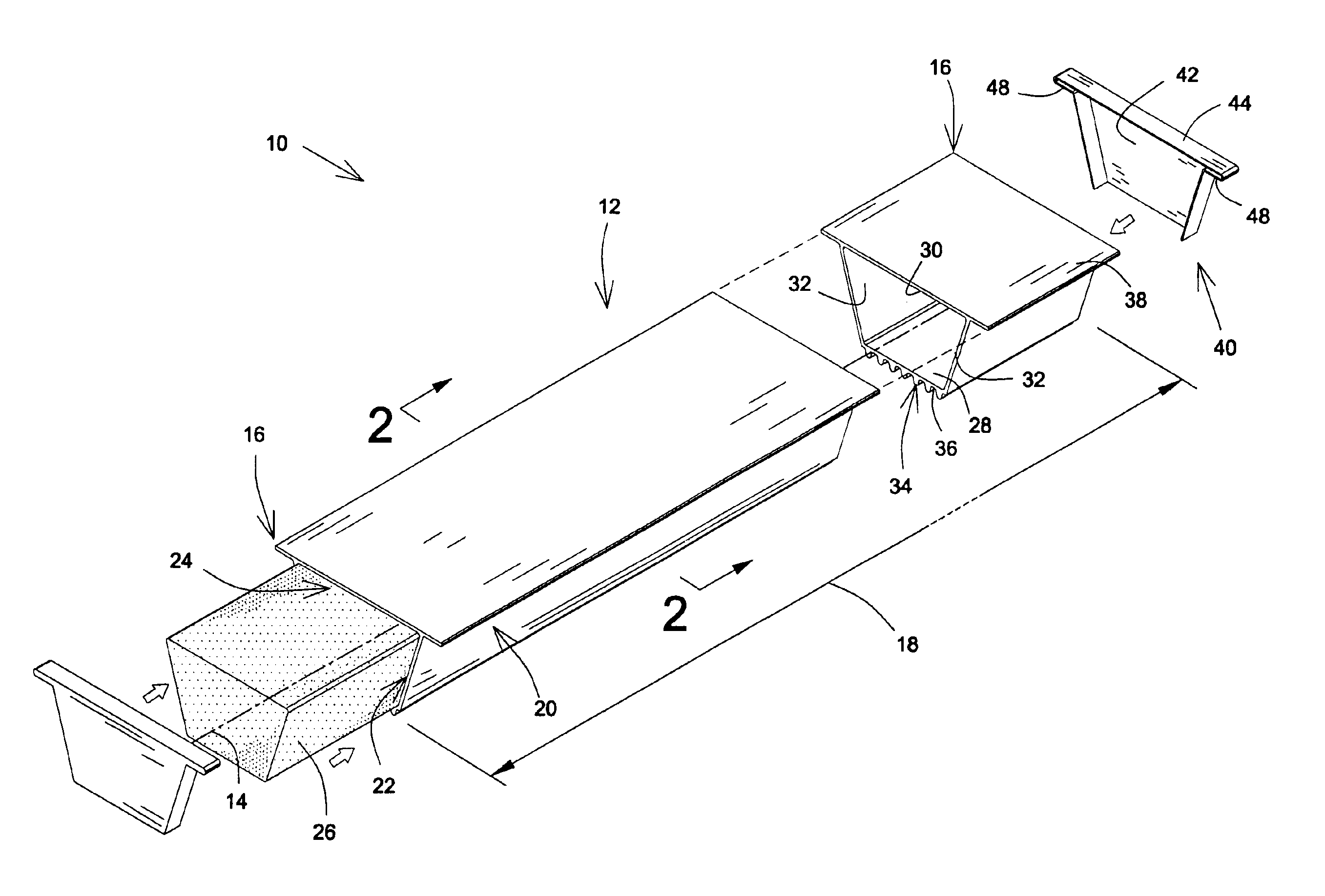
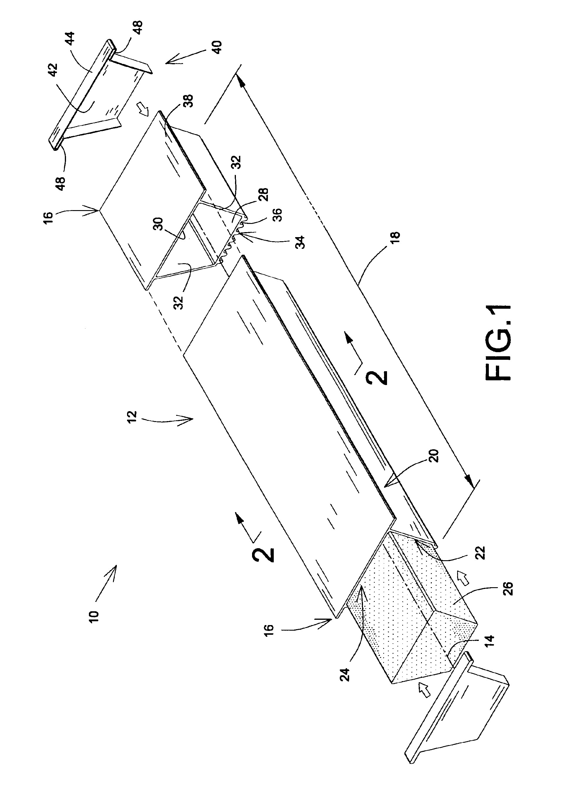
Referring to FIG. 1, there is shown a pontoon 10, in accordance with an embodiment of the present invention. The pontoon 10 includes a generally elongated shell 12. The shell 12 defines a shell longitudinal axis 14, a pair of generally opposed shell longitudinal ends 16 and a shell length 18 extending along the shell longitudinal axis 14 between the shell longitudinal ends 16.

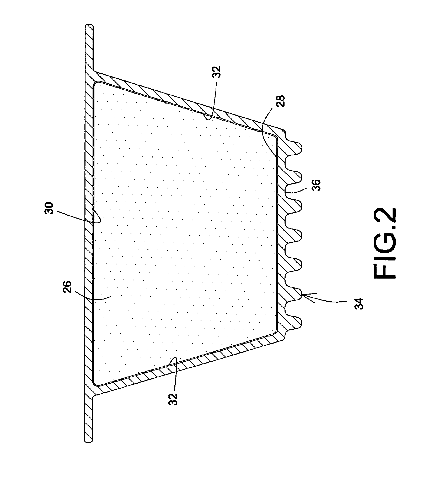
The shell 12 has a shell peripheral wall 20 surrounding a shell inner volume 22. The shell peripheral wall 20 defines at least one end aperture 24 extending into the shell inner volume 22 from one of the shell longitudinal ends 16. Typically, as illustrated throughout the figures, the shell peripheral wall 20 defines a pair of opposed end apertures 24 (only one of which is shown in FIG. 1) both extending into the shell inner volume 22 from opposed shell longitudinal ends 16. Alternatively, the shell peripheral wall 20 may define a single end aperture 24, the opposed section of the shell peripheral wall 20 being...


PUM

PropertyMeasurementUnit
Volumeaaaaaaaaaa

Abstract

A pontoon includes a generally elongated shell made of at least two shell segments assembled in an end-to-end configuration at adjacent male and female segment connecting ends. Each segment has a segment peripheral wall surrounding a segment inner volume. Each segment defines at least one end aperture extending into the segment inner volume from one of the segment longitudinal ends. The female segment connecting end is a longitudinal end portion of the segment peripheral wall. A filling component is positioned within the segment inner volumes. The filling component is made out of a buoyant material longitudinally and slidably inserted into the end apertures. The volume of the filling component into the shell is such that the combination of the shell and the filling component forms a buoyant combination. A mold for the fabrication of the shell segments is also disclosed.

Description

FIELD OF THE INVENTIONThe present invention relates to the general field of floating accessories and is particularly concerned with a pontoon with a shell therefor.BACKGROUND OF THE INVENTIONWith the advent of the so-called leisure society and the concurrent trend towards outdoor activities, recreational facilities are being elaborated in areas where water is available. Such recreational facilities typically require docks and marinas so that boats can be used conveniently. Also, recreational crafts such as pontoon boats are becoming increasingly popular.In constructing marinas or small boats harbors, it is typically desirable to use a floating wharf structure which is accessible from land and has one or more fingers extending out into the body of water. The floating platforms used for building marinas are sometimes also used with some modifications as diving platforms and the like.Generally, floating platforms include an upper decking material supported by a series of transverse and...

Claims


Application Information

Patent Timeline
IPC IPC(8): B63B5/00B63B5/24B63B9/00B63B9/06B63B35/34E02B3/06B63B35/38
CPCB63B5/24B63B9/06E02B3/064B63B35/34B63B35/38B63B2231/50
Inventor TREPANIER, PAUL
Owner TREPANIER PAUL
Why Eureka
Try Eureka