Impact energy transmitting arrangement

a technology of energy transmission and impact, which is applied in the direction of bumpers, vehicle components, pedestrian/occupant safety arrangements, etc., can solve the problems affecting the safety of pedestrians, and reducing the amount of energy which arises in low-speed collisions between vehicles and pedestrians. , to achieve the effect of reducing the risk of injury to pedestrians and simple operation

Inactive Publication Date: 2005-03-29
FORD GLOBAL TECH LLC
View PDF13 Cites 14 Cited by
  • Summary
  • Abstract
  • Description
  • Claims
  • Application Information

AI Technical Summary

Benefits of technology

It is therefore an object of the present invention to provide an impact energy transmitting arrangement which is simple in

Problems solved by technology

Obviously, the risk of injury to occupants of vehicles is increased at higher speeds.
Due to the relatively light weight of most pedestrians, the amount of energy which arises in a low speed collision between a vehicle and a pedestrian is relatively low.
This implies that the deformation zones of the vehicle are not caused to deform to an

Method used


Image

  • Impact energy transmitting arrangement
  • Impact energy transmitting arrangement
  • Impact energy transmitting arrangement

Examples


first embodiment

the impact energy transmitting arrangement of the present invention is designed to be operable in the following manner.

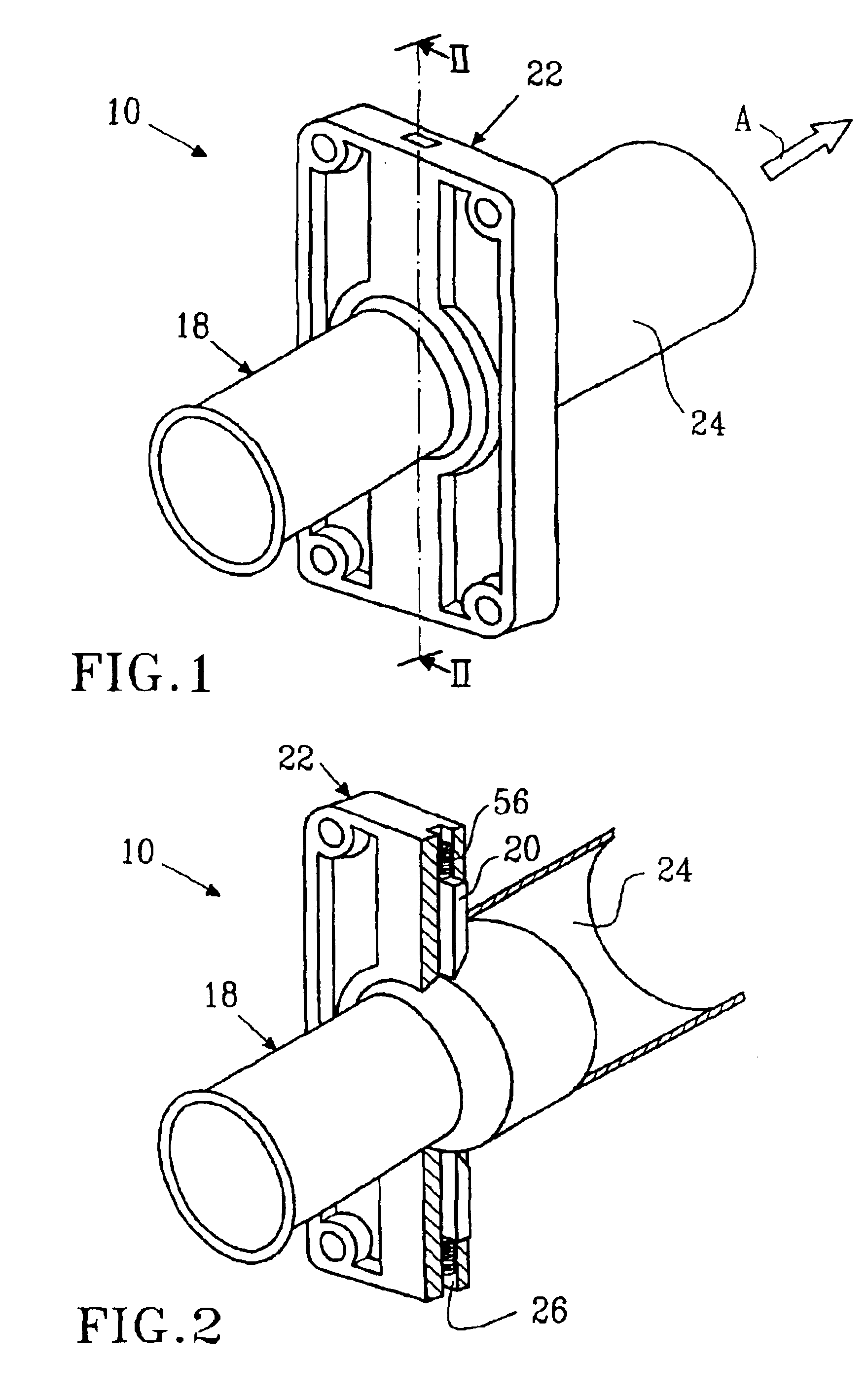
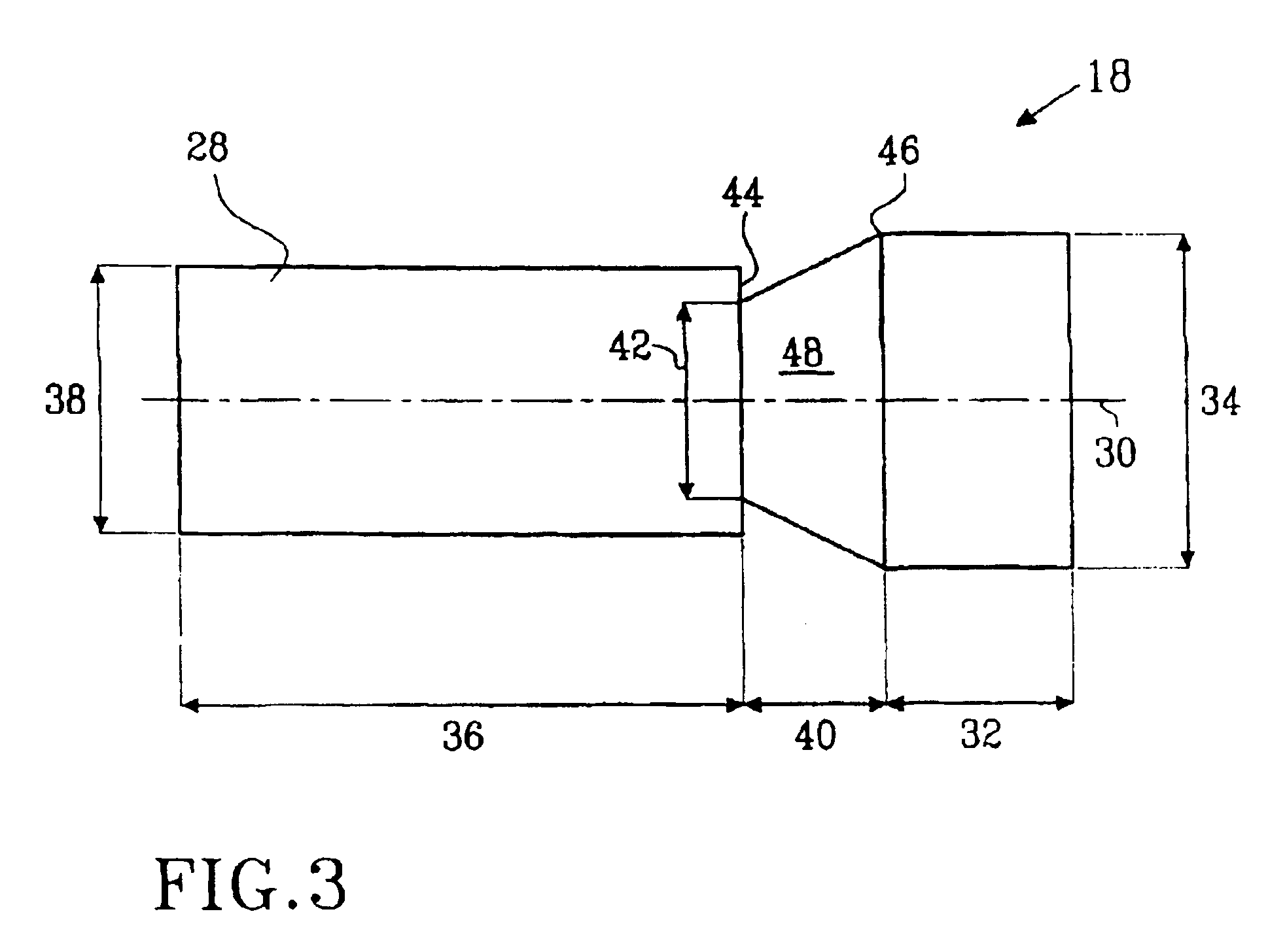
The arrangement 10 is illustrated in FIG. 4A in its non-influenced condition, i.e. before impact between the vehicle upon which it is mounted and a foreign body. The first region 32 of the elongate member projects into the first guide portion 24 of the housing 22. As previously mentioned, the first end 52 of the abutment member 50 abuts against the first region 32 of the elongate member at a location substantially corresponding to the location 46 at the intersection between the first and third regions of the elongate member.

If the vehicle to which the arrangement 10 is mounted is involved in a low speed collision with a foreign body, for example the velocity of the vehicle is below 30 km / h, preferably below 20 km / h and is most preferably about 15 km / h, the arrangement will be caused to adopt the condition illustrated in FIG. 4B. Thus, upon impact, the elongate membe...

second embodiment

the impact energy transmitting arrangement of the present invention is designed to be operable in the following manner.

The arrangement 70 is illustrated in FIG. 7A in its non-influenced condition, i.e. before impact between the vehicle upon which it is mounted and a foreign body. It is to be noted that there is a distance 134 defining a gap between the first abutment end 104 of the abutment member 100 and the first abutment surface 118 of the first recess 120 in the housing 76.

If the vehicle to which the arrangement 10 is mounted is involved in a collision in which the energy which arises is relatively low, for example for a typical the low speed collision of the vehicle with a pedestrian with the velocity of the vehicle being below 30 km / h, preferably below 20 km / h and being most preferably about 15 km / h, the arrangement will be caused to adopt the condition illustrated in FIG. 7B. Thus, upon impact, the elongate member 78 is caused to accelerate in the direction of arrow A through...

third embodiment

the impact energy transmitting arrangement of the present invention is designed to be operable in the following manner.

The arrangement 140 is illustrated in FIG. 10A in its non-influenced condition, i.e. before impact between the vehicle upon which it is mounted and a foreign body, with the abutment member 178 being accommodated in the resting hollow 182 in the second arm 158 of the pivotal member 146. If the vehicle to which the arrangement 140 is mounted is involved in a low speed collision with a foreign body, for example the velocity of the vehicle is below 30 km / h, preferably below 20 km / h and is most preferably about 15 km / h, the arrangement will be caused to adopt the condition illustrated in FIG. 10B. Thus, upon impact, the pivotal member 146 is caused to accelerate about the pivot point 150. Due to the relatively low quantity of energy which arises during such a low speed impact, the rate of acceleration of the pivotal member will be such that the spring 180 maintains the a...


PUM


Abstract

An impact energy transmitting arrangement (10) for transmitting energy, which arises during impact between a vehicle (12) on which the arrangement (10) is mounted and a foreign body, to a vehicle structure (14). The arrangement includes first means (18) displaceable in a first direction, and second means (20) adapted for co-operation with the first means. The first and second means are operable such that the arrangement, below a first predetermined value of a parameter representative of the energy to be transmitted, presents a first resistance-to-displacement value and, above the first predetermined value, presents a second resistance-to-displacement value. The first resistance-to-displacement value is greater than the second resistance-to-displacement value. In this manner, a bumper assembly which is stiff at very low speeds is rendered less stiff at higher speeds which otherwise could cause injury to pedestrians.

Description

TECHNICAL FIELDThe present invention relates to an impact energy transmitting arrangement for transmitting energy, which arises during impact between a vehicle on which said arrangement is mounted and a foreign body, to the vehicle structure. The invention further relates to a method of transmitting energy, which arises during impact between a vehicle on which said arrangement is mounted and a foreign body, to the vehicle structure.BACKGROUND OF THE INVENTIONMotor vehicle manufacturers are constantly striving to provide vehicles which, in the event of a collision, reduce the risk of injury to persons involved in the collision. These persons may be occupants of the vehicle or a pedestrian which is struck by the vehicle. To this end, vehicles are nowadays designed with so-called deformation zones which deform in a controlled manner to thereby absorb energy which arises during impact between the vehicle and an object. The amount of energy which arises in a collision is proportional to ...

Claims


Application Information

Patent Timeline
IPC IPC(8): B60R21/34B60R19/28B60R19/24B60R19/26
CPCB60R19/28B60R21/34B60R2019/262
Inventor ERICSSON, MATTIAS
Owner FORD GLOBAL TECH LLC
Why Eureka
Try Eureka