Adjustable transverse connector

a transverse connector and adjustable technology, applied in the field of transverse connectors, can solve the problems of one or more problems, the inability of the transverse connector to connect rods that are skewed relative to each other, and the need to stabilize the spine of a patient, etc., to achieve the effect of convenient bending of the transverse connector

Inactive Publication Date: 2005-03-29
ZIMMER SPINE INC
View PDF76 Cites 326 Cited by
  • Summary
  • Abstract
  • Description
  • Claims
  • Application Information

AI Technical Summary

Benefits of technology

Transverse connectors may be used to stabilize and inhibit movement of an orthopedic stabilization system. A transverse connector may be a fixed length transverse connector or an adjustable transverse connector. An embodiment of a fixed length transverse connector has a body configured to resist bending of the transverse connector. An alternate embodiment of a fixed length transverse connector is configured to allow the body to be bent to allow elongated member openings of the connector to be oriented relative to elongated members. Bending the fixed length transverse connector may also allow for some length adjustment of the transverse connector. A bendable fixed length transverse connector may include indentations that facilitate bending the transverse connector. An adjustable transverse connector may allow for adjustment of axial position, rotation, and / or angulation of a first elongated member opening relative to a second elongated member opening.
Another advantage of a transverse connector is that the transverse connector may have a thin and low profile. The low profile of the transverse connector may allow the transverse connector to have a minimal effect on adjacent tissue when the transverse connector is installed within a patient. The thin profile may allow the transverse connector to be easily positioned at desired locations on a stabilization system. Further advantages of transverse connectors may include that the transverse connectors are sturdy, durable, light weight, simple, efficient, reliable and inexpensive; yet the transverse connectors may also be easy to manufacture, install, and use.

Problems solved by technology

For example, disease or trauma may result in the need to stabilize the spine of a patient.
Many transverse connectors present one or more problems for a surgical team that installs the transverse connectors.
Some of the problems associated with transverse connectors include the need to pre-load connectors on a rod, high profiles, wide profiles, separate component fasteners, and proper tightening of threaded fasteners.
Also, the ability of a transverse connector to connect rods that are skewed relative to each other may be problematic.
The use of preloaded connectors may require significant pre-operative planning.
The use of preloaded connectors may inhibit a surgical team's ability to make changes that are needed to meet conditions presented during insertion of the stabilization system in the patient.
These profiles may cause surgical complications to tissue and bone adjacent to the connector.
A high profile transverse connector may result in abrasion of tissue adjacent to the transverse connector.
A separate component fastener, such as a nut, may be difficult to properly position and secure during an installation procedure.
Not tightening a threaded fastener enough may allow movement of the transverse connector.
Over tightening a threaded fastener may result in damage to the fastening system that could cause failure of the transverse connector.
Using a torque wrench may be burdensome to a surgical team that installs a stabilization system.
Positioning a pair of rods within such a transverse connector may be difficult during installation of the transverse connector in a patient.
Some transverse connectors cannot be adjusted to accommodate rods that are horizontally and / or vertically skewed.

Method used


Image

  • Adjustable transverse connector
  • Adjustable transverse connector
  • Adjustable transverse connector

Examples


Embodiment Construction

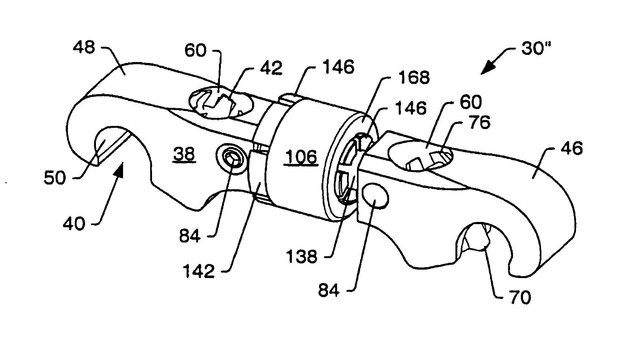
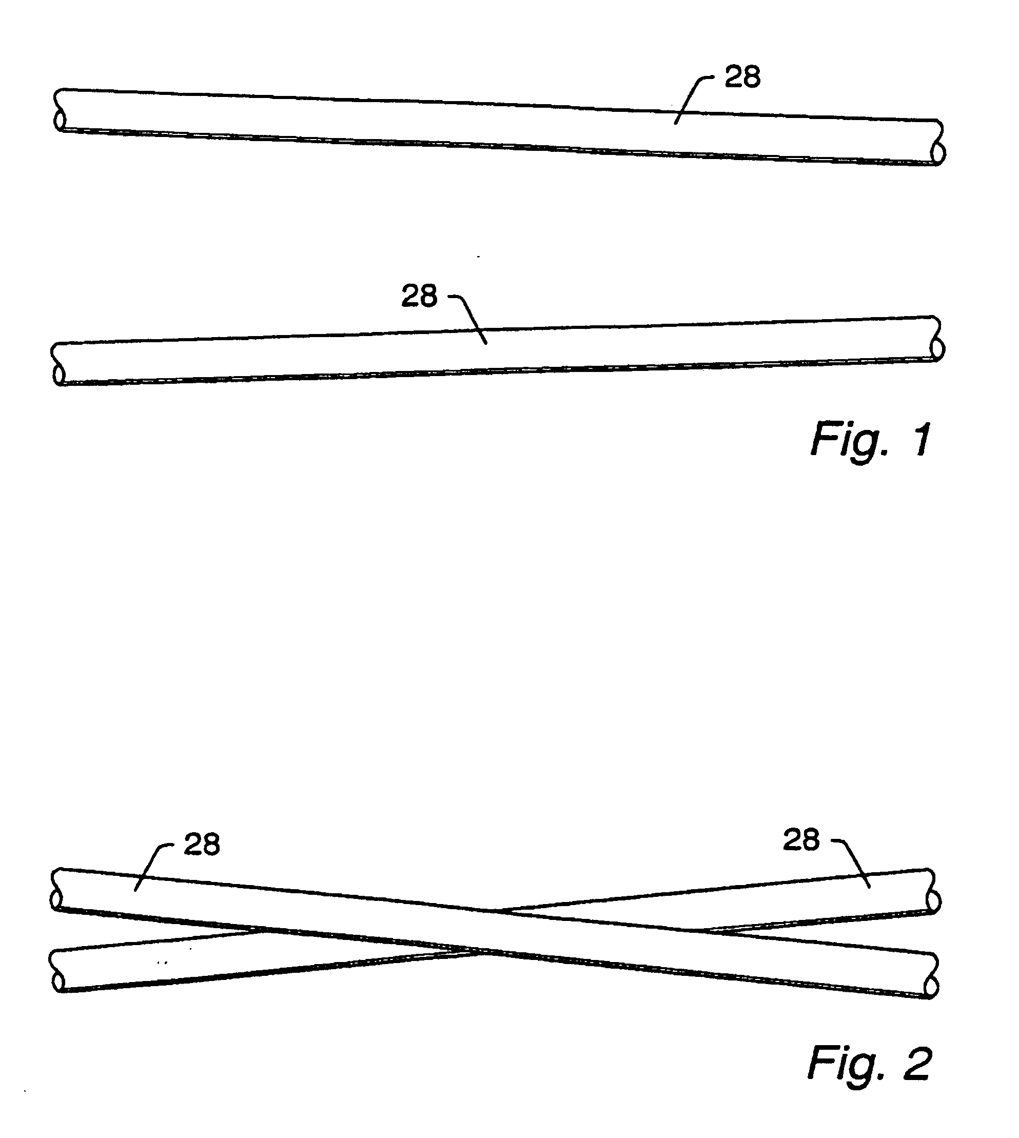
With reference to the drawings, transverse connectors are denoted generally as 30. Transverse connectors 30 may be used to connect elongated members 28 of an orthopedic stabilization system 32 together. Transverse connectors 30 may provide rigidity to the orthopedic stabilization system 32. Transverse connectors 30 may also inhibit undesired motion of the orthopedic stabilization system 32. Transverse connectors 30 may be fixed length transverse connectors or adjustable length transverse connectors. The elongated members 28 of an orthopedic stabilization system 32 may be coupled to bones 34 by fixation elements 36. The fixation elements 36 may be, but are not limited to, hooks and bone screw connectors. In an embodiment, the elongated members 28 are spinal rods that are coupled to vertebral bodies 34 by fixation elements 36. The spinal rods 28, fixation elements 36, and transverse connectors 30 form part of a spinal stabilization system 32. FIG. 3 shows a portion of an embodiment of...


PUM


Abstract

A transverse connector may be attached to rods of an orthopedic stabilization system. The rods of the stabilization system may be non-parallel and skewed in orientation relative to each other. The transverse connector may include two members that are joined together by a fastener. The transverse connector may be adjustable in three separate ways to allow the transverse connector to attach to the rods. The length of the transverse connector may be adjustable. The rod openings of the transverse connector may be partially rotatable about a longitudinal axis of the transverse connector. Also, a first member may be angled towards a second member so that the transverse connector can be attached to rods that are diverging. The transverse connector may include cam locks that securely attach the transverse connector to the rods. Rotating a cam locks may extend a rod engager into a rod opening. The rod engager may be a portion of the cam lock. The extension of the rod engager into a rod opening may push a rod against a body of the transverse connector to form a frictional engagement between the transverse connector, the rod, and the rod engager.

Description

BACKGROUND OF THE INVENTION1. Field of the InventionThe present invention generally relates to bone stabilization systems, and more particularly to a transverse connector for connecting adjacent rods of orthopedic stabilization systems. The transverse connector, or cross-link, may connect together adjacent spinal rods of a spinal stabilization system.2. Description of Related ArtBone disorders, degenerative conditions, or trauma may result in a need to stabilize a bone or bones of a patient with an orthopedic stabilization system. For example, disease or trauma may result in the need to stabilize the spine of a patient. A variety of systems may be used to stabilize a spine. A spinal stabilization system may generally be classified as an anterior, lateral, or posterior system according to a position of the system relative to the spine. Posterior stabilization systems often include pairs of vertically aligned rods for stabilizing both short and long segments of a spine.An orthopedic s...

Claims


Application Information

Patent Timeline
Patent Type & Authority Patents(United States)
IPC IPC(8): A61B17/70
CPCA61B17/7052A61B17/7049A61B17/7011
Inventor MCBRIDE, G. GRADYJONES, ROBERT J.KOYSH, SCOTT D.
Owner ZIMMER SPINE INC
Why Eureka
Try Eureka