Motion picture analyzing system

a motion picture and motion picture technology, applied in the field of motion picture analyzing systems, can solve the problems of difficult to analyze the motion of objects in motion pictures, difficult to realize high-speed analysis, and inability to meet the needs of users, etc., to achieve accurate analysis, simple configuration, and high speed

Inactive Publication Date: 2005-03-29
RIKEN
View PDF1 Cites 1 Cited by
  • Summary
  • Abstract
  • Description
  • Claims
  • Application Information

AI Technical Summary

Benefits of technology

According to the present invention, after two kinds of images (a first addition image and a second addition image respectively including images of still pictures at different discrete time points at different ratios) are generated by sequentially timewise adding images of still pictures at individual discrete time points included in a motion picture to be analyzed, a motion component in the motion picture to be analyzed is detected by comparing the two kinds of images generated in this manner. Here, since the two kinds of images to be compared include events occurring at different discrete time points, the result obtained by comparing the first addition image with the second addition image is not discrete, even if the photographing interval of the still pictures is discrete. Therefore, even when the movement of an object to be photographed is fast, the motion components in the motion picture can accurately be analyzed at a high speed with a simple configuration. Particularly, a circuit which realizes such processing can easily be realized by hardware, and the two kinds of images to be compared are obtained by temporally adding a plurality of images. Therefore, the noiseproof property can be improved by the temporal averaging effect, without sacrificing time resolution.
Moreover, according to the present invention, the movement direction in the motion picture to be analyzed is detected by taking out the first pixel group located in a predetermined area from the generated first addition image, as well as taking out the second pixel group located in an area corresponding to the predetermined area from the second addition image, and then comparing the taken out first pixel group and the taken out second pixel group, while spatially shifting these groups. As a result, the movement direction in the motion picture can be analyzed with a simple configuration.

Problems solved by technology

With such a conventional method, however, continuous motion of an object is caught at a discrete photographing interval; thus, as the motion of the object becomes faster, it becomes difficult to find corresponding pixels by temporally comparing the images of the consecutive still pictures, and it also becomes difficult to analyze the motion of the object in a motion picture.
However, with the method (1), since it is necessary to reexamine the configuration of the photographing equipment basically to shorten the photographing interval, it may not be practical in view of the cost.
With the method (2), since a lot of calculation time becomes necessary for the interpolation processing by the software, it is difficult to realize high-speed analysis.

Method used


Image

  • Motion picture analyzing system
  • Motion picture analyzing system
  • Motion picture analyzing system

Examples


Embodiment Construction

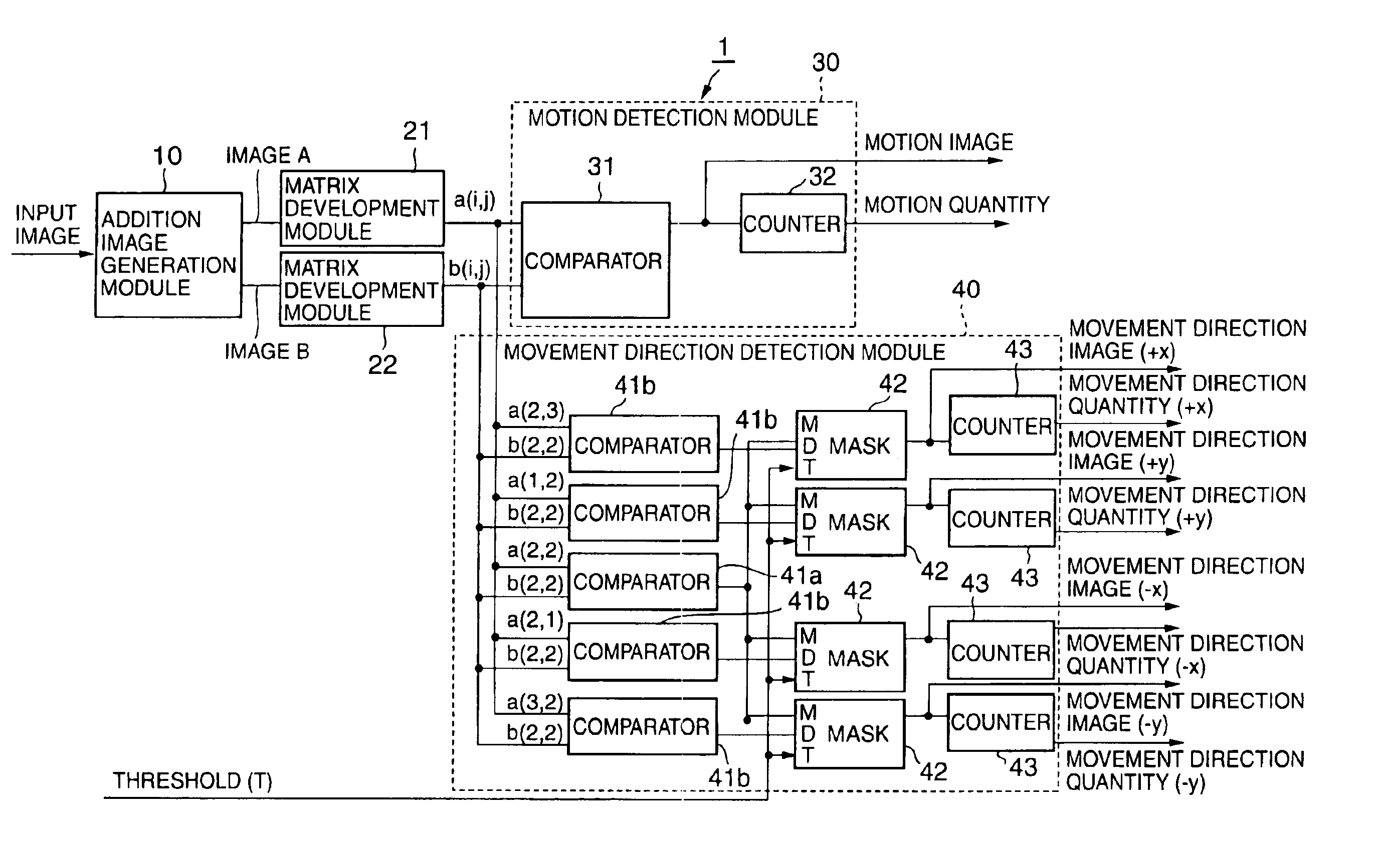
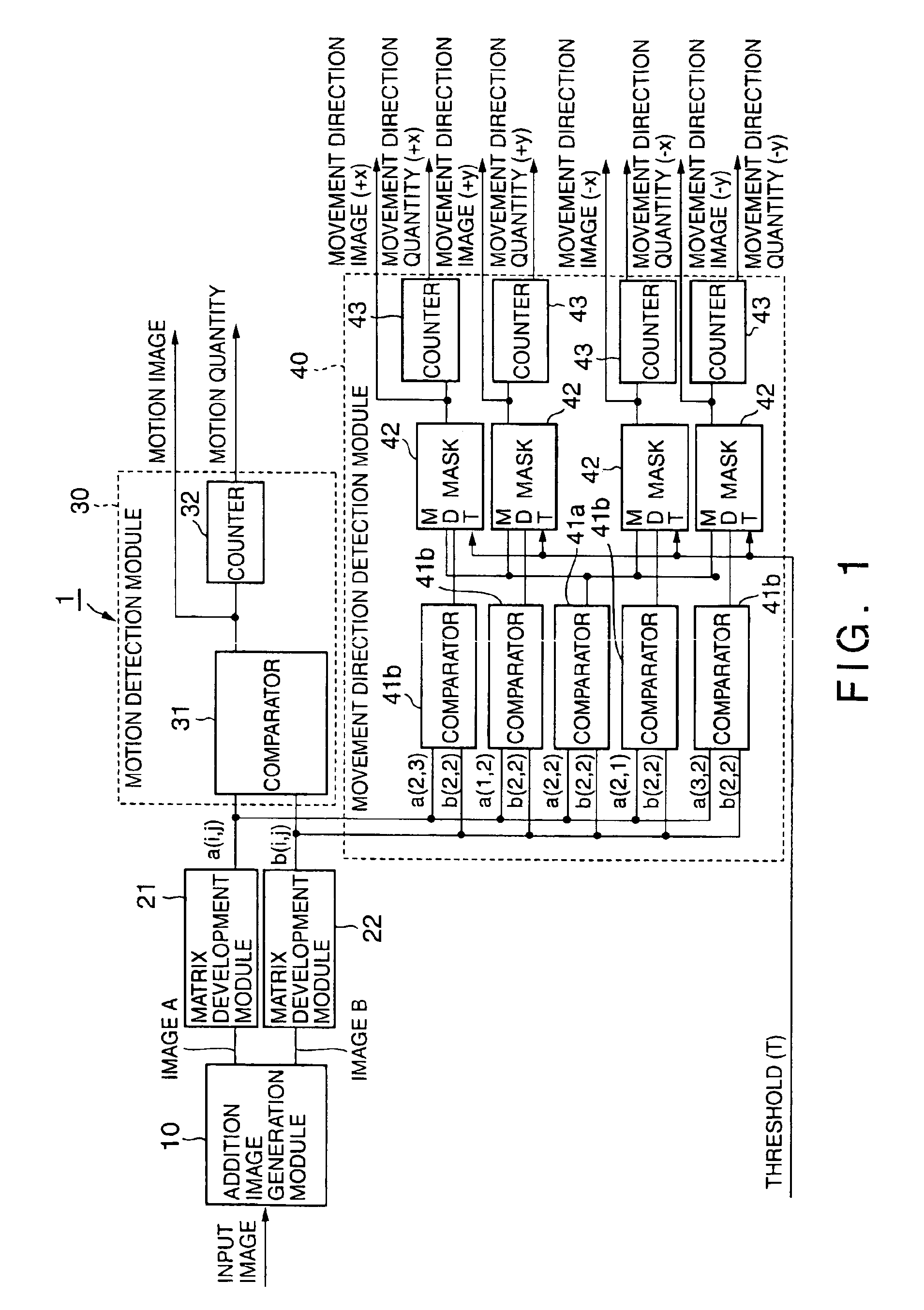
At first, the overall configuration of the motion picture analyzing system according to an embodiment of the present invention will be described, with reference to FIG. 1.

As shown in FIG. 1, the motion picture analyzing system 1 includes an addition image generation module 10, matrix development modules 21 and 22, a motion detection module 30, and a movement direction detection module 40.

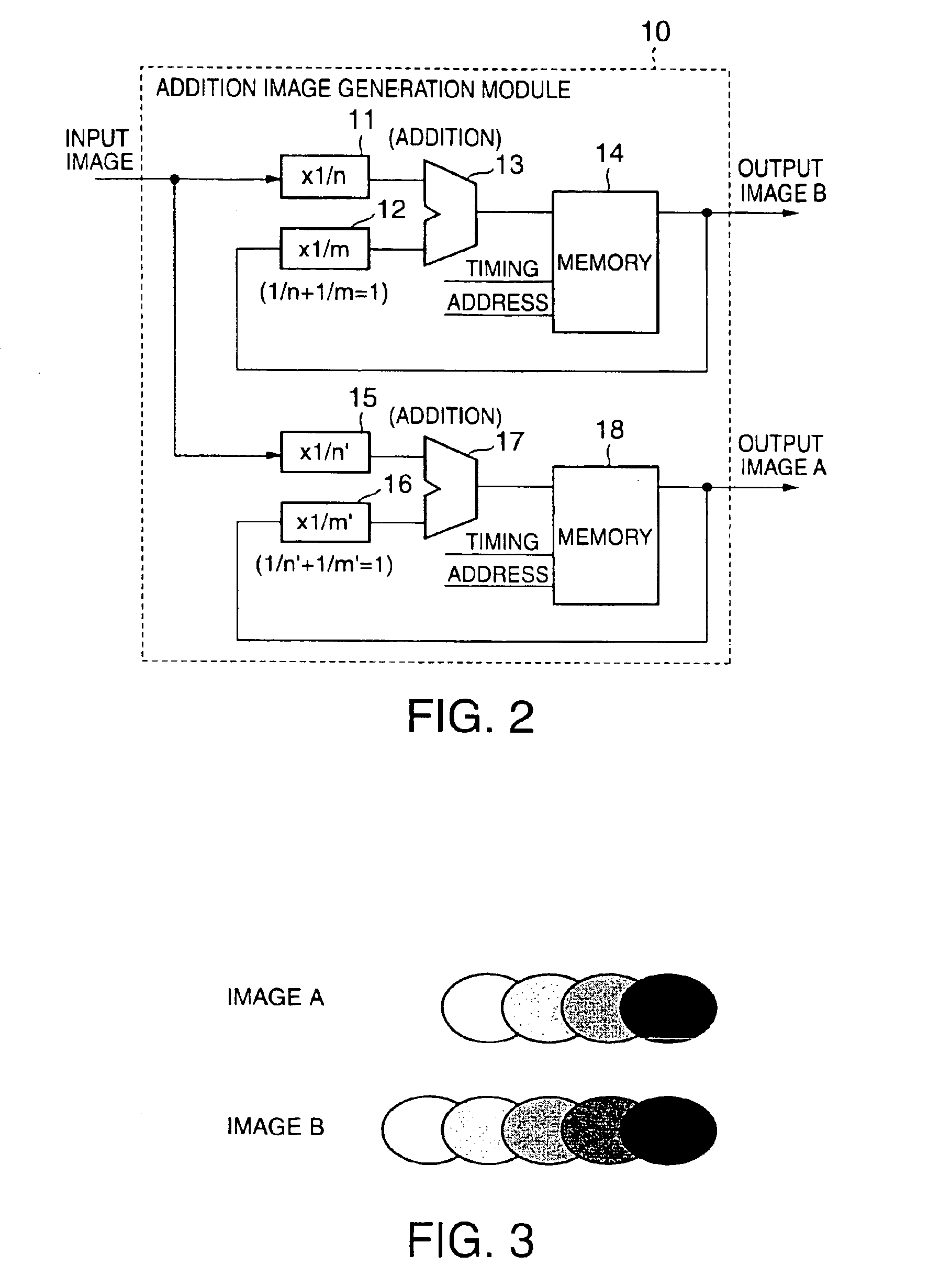
Among the above modules, the addition image generation module 10 is for generating two kinds of addition images (image A and image B). The two kinds of addition images respectively includes images of still pictures at different discrete time points with the images being added at different ratios. The images (input images) of still pictures are sequentially timewise added at individual discrete time points included in the motion picture to be analyzed.

The matrix development modules 21 and 22 are for respectively taking out pixel groups (first pixel group a(i, j) and second pixel group b(i, j)) locate...


PUM


Abstract

An addition image generation module 10 sequentially timewise adds images (input images) of still pictures at individual discrete time points included in a motion picture to be analyzed, thereby generating two kinds of addition images (image A and image B), respectively including images of still pictures at different discrete time points with the images being added at different ratios. Matrix development modules respectively take out pixel groups (first pixel group a(i, j) and second pixel group b(i, j)) located in a predetermined area (for example, in an area having a size of 3×3), from the generated image A and image B. A motion detection module compares the taken out first pixel group a(i, j) and second pixel group b(i, j), to detect a motion component in the motion picture to be analyzed. A movement direction detection module compares the taken out first pixel group a(i, j) and second pixel group b(i, j), while spatially shifting these groups, to detect the movement direction in the motion picture to be analyzed.

Description

BACKGROUND OF THE INVENTION1. Field of the InventionThe present invention relates to a motion picture analyzing system that analyzes a motion picture such as a video image, and more specifically, relates to a motion picture analyzing system, a motion picture analyzing method and a motion picture analyzing program, all of which analyze the motion of an object in a motion picture.2. Description of Related ArtGenerally, a motion picture such as a video image consists of a group of still pictures photographed at a discrete time interval (photographing interval). Conventionally, when the motion of an object in a motion picture is analyzed, a method, in which a pixel having a temporal change is extracted by comparing images of still pictures photographed at different discrete time points, is generally adopted.With such a conventional method, however, continuous motion of an object is caught at a discrete photographing interval; thus, as the motion of the object becomes faster, it becomes ...

Claims


Application Information

Patent Timeline
Patent Type & Authority Patents(United States)
IPC IPC(8): G03B19/18G03B19/00G06T7/20H04N7/01H04N5/14
CPCH04N5/145G06T7/2053G06T7/254
Inventor YAMADA, HITOSHIICHIKAWA, MICHINORI
Owner RIKEN
Why Eureka
Try Eureka