
Mattress with semi-independent pressure relieving pillars

a mattress and semi-independent technology, applied in the field of mattresses, can solve the problems of tissue decay and ulcer formation, inconvenient manufacturing, and increased risk of decubitus ulcer formation, and achieve the effect of alleviating or minimizing the occurrence of decubitus ulcers, and being easy and relatively affordable to manufactur

Inactive Publication Date: 2005-04-05
HUNTLEIGH TECH LTD
View PDF17 Cites 90 Cited by
  • Summary
  • Abstract
  • Description
  • Claims
  • Application Information

AI Technical Summary

Benefits of technology

An object of the present invention is to provide a non-mechanized pressure-reducing mattress that provides therapeutic benefits to a person confined thereto for a substantial period.
An even yet further object of the present invention is to provide a decubitus preventing or alleviating mattress containing semi-independent pressure relieving pillars which is more economical than those of equal efficacy known to the prior art where these pillars are provided in both the top and bottom surfaces of the mattress.

Problems solved by technology

Patients and other persons restricted to bed for extended periods incur the risk of decubitus ulcers formation.
Tissue trauma may then set in with the resultant tissue decay and ulcer formation.
However, such movement is, either not always possible or is in some instances neglected.
Additionally, even shorter bed rest periods by healthy individuals on a mattress that neither relieves nor reduces the pressure exerted on the user is likely to be considered uncomfortable.
Conversely, a mattress that provides insufficient firmness or support is also likely to be uncomfortable.
Some relatively expensive motorized and / or dynamic devices have been quite successful in solving these problems.
However, their cost and relative complexity drastically reduce the breadth of market to which such devices can be effectively offered.
Therefore prior to the filing of the parent application cited above, no non mechanized device has been wholly successful in meeting these needs, at a cost which, in view of government cutbacks in such programs as Medicare, and stringent, possibly draconian, cost restrictions, would make such devices readily accessible.

Method used


Image

  • Mattress with semi-independent pressure relieving pillars
  • Mattress with semi-independent pressure relieving pillars
  • Mattress with semi-independent pressure relieving pillars

Examples


example 1

A piece of foam approximately 35″×64″×5″ deep, having the proper characteristics is selected. The following steps are performed upon the foam:

1. Place foam flat on cutting surface.

2. Align foam to be parallel with cutting wires so that the foam is centered along the width of wires.

3. Lower the hot cutting wires 2″ into the foam; these wires are preheated to a suitable temperature by electric current.

4. If desired leave the heated wires in place momentarily after the desired depth has been reached.

5. Raise the cutting wires out of the foam.

6. Rotate the foam 90 degrees and repeat steps 1-5.

The cut foam is now a body support cushion, and assembled as part of a completed mattress embodying the present invention.

example 2

A piece of foam is treated in accordance with Example 1. This piece of foam is then rotated so that the cut side is downward. The following steps are then performed upon the foam:1. Place foam flat on cutting surface.2. Align foam to be parallel with cutting wires so that the foam is centered along the width of wires.3. Lower the hot cutting wires 2″ into the foam; these wires are preheated to a suitable temperature by electric current.4. If desired leave the heated wires in place momentarily after the desired depth has been reached.5. Raise the cutting wires out of the foam.6. Rotate the foam 90 degrees and repeat steps 1-4.

The cut foam is now a body support cushion having two opposed arrays of semi-independent pillars. It may now be assembled as part of a completed mattress embodying the present invention.


PUM


Abstract

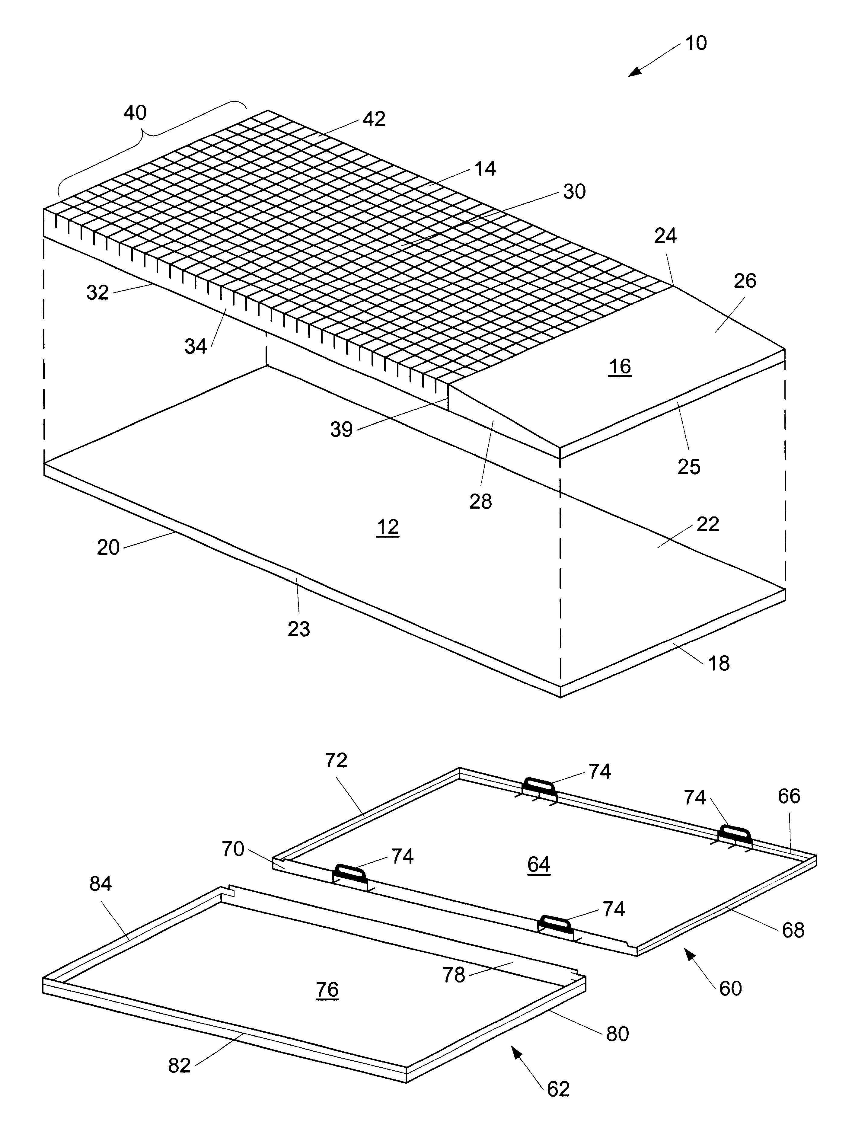
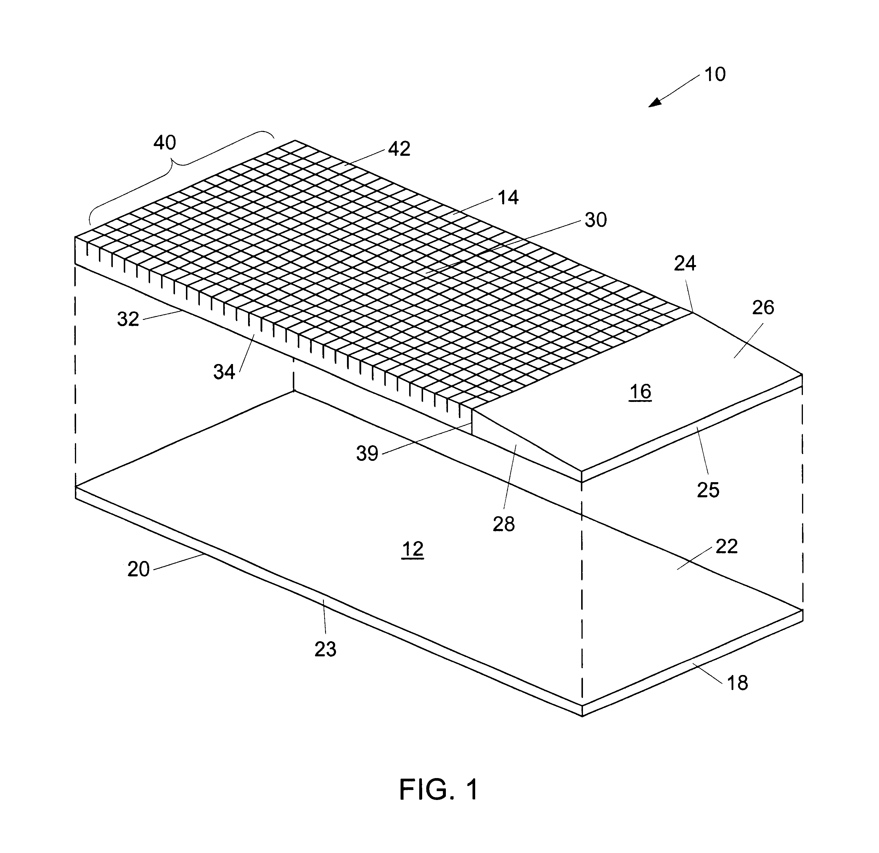
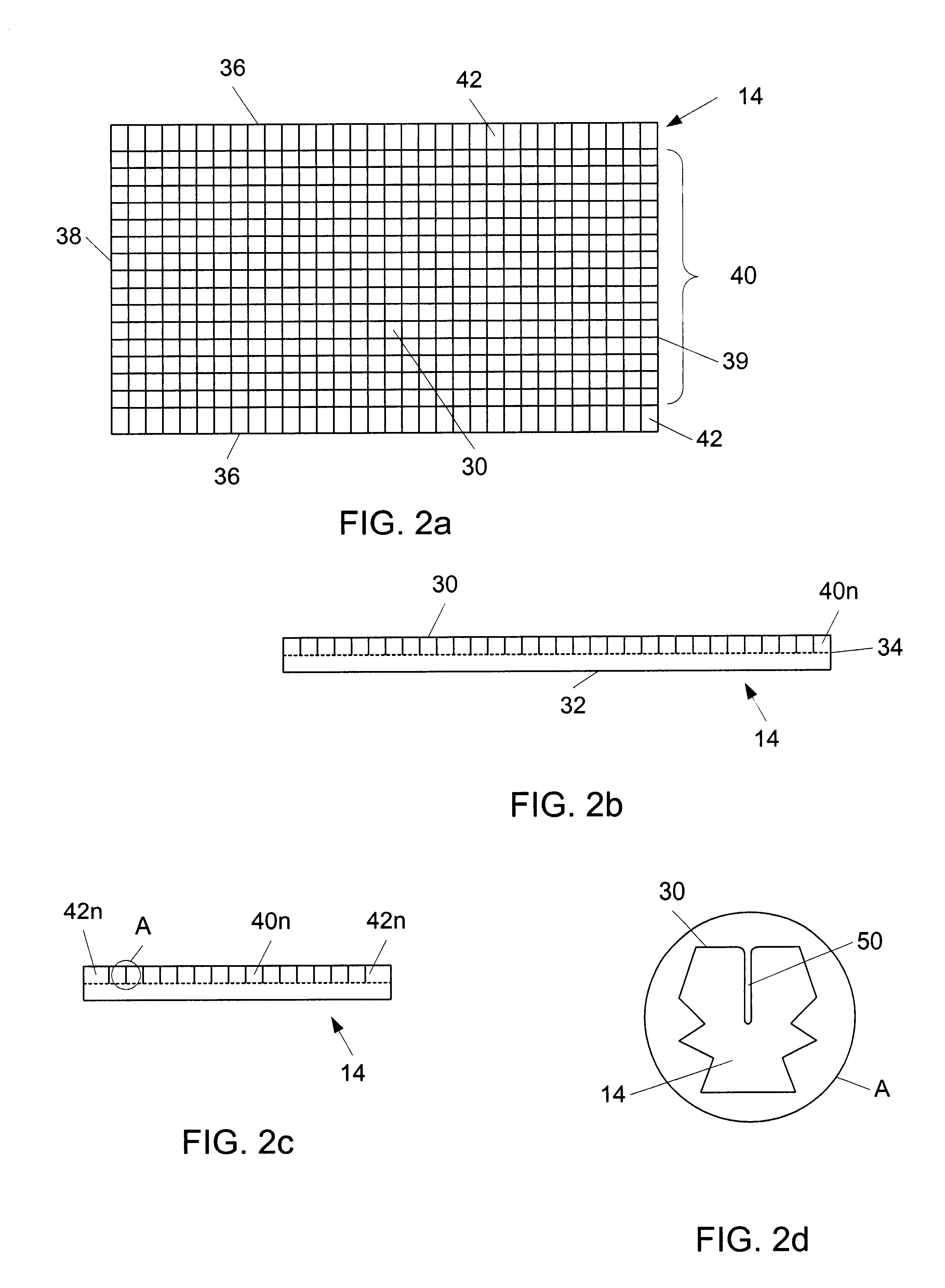
A foam core cushion mattress assembly provides semi-independent foam pillars on the upper surface of the mattress. The mattress may be unitary, or comprise multiple cushioning components, possibly base, body support and foot cushions. The body support cushion is constructed from a flat, rectangular solid, foam element whose upper surface is cut into an array of rectangular solid pillars, preferably by a hot wire cutting method. The array of rectangular solid pillars is grouped into a central array comprising pillars with generally square top surfaces and edge rows of rectangular solid pillars having rectangular top surfaces. The depth of the hot wire cuts into the surface of the body support cushion is preferably approximately one-half the overall thickness of the body support cushion or approximately three fourths of the length of the shortest face of the pillar. A zippered fabric cover removeably envelops the assembled cushioning components. The resultant structure defines a plurality of semi-independently compressible pillars that support a reclining, or supine patient. The pillars may also be cut into the top and bottom surfaces of the cushion for enhanced pressure relieving effects. Methods of manufacture, and treatment and alleviation of decubitus ulcer formation are also presented.

Description

BACKGROUND OF THE INVENTION1. Field of the InventionThe present invention relates generally to mattresses for use in association with beds and other support platforms. The present invention relates more specifically to a foam containing mattress assembly having a pressure relieving structure comprising semi-independent foam pillars, on either one, or two surfaces of such a mattress, a method of manufacture thereof, and a method of treating decubitus ulcers therewith.2. Description of the Related ArtPatients and other persons restricted to bed for extended periods incur the risk of decubitus ulcers formation. Decubitus ulcers (also referred to as bed sores, pressure sores or pressure ulcers) are formed due to an interruption of blood flow in the capillaries below skin tissue due to pressure against the skin. The highest risk areas for such ulcer formation are those areas where there exists a bony prominence, which tends to shut down capillaries sandwiched between the bony prominence ...

Claims


Application Information

Patent Timeline
IPC IPC(8): A47C27/14A61G7/057
CPCA47C27/146A61G7/05707A47C27/148
Inventor PHILLIPS, BRUCESANDERS, BLANENIEDERKROM, CHRIS
Owner HUNTLEIGH TECH LTD
Learn More