Tool extension assembly with quick release lock mechanism

Active Publication Date: 2005-04-05
THE SHERWIN-WILLIAMS CO
View PDF20 Cites 23 Cited by
  • Summary
  • Abstract
  • Description
  • Claims
  • Application Information

AI Technical Summary

Benefits of technology

In an alternative embodiment, the tool extension assembly further includes a flange joined to the side wall. The flange has a plurality of interior side surfaces at least partially defining a multifaceted socket that is in communication with the bore. Moreover, the connecting device further includes a base from which the side wall extends. The base includes a plurality of side surfaces that defi

Problems solved by technology

One disadvantage of such a threaded connection is that during use, the paint roller may rotate so as to unscrew the extension pole from the paint roller.
Since the latchi

Method used


Image

  • Tool extension assembly with quick release lock mechanism
  • Tool extension assembly with quick release lock mechanism
  • Tool extension assembly with quick release lock mechanism

Examples


Example

It should be noted that in the detailed description that follows, identical components have the same reference numerals, regardless of whether they are shown in different embodiments of the present invention. It should also be noted that in order to clearly and concisely disclose the present invention, the drawings may not necessarily be to scale and certain features of the invention may be shown in somewhat schematic form.

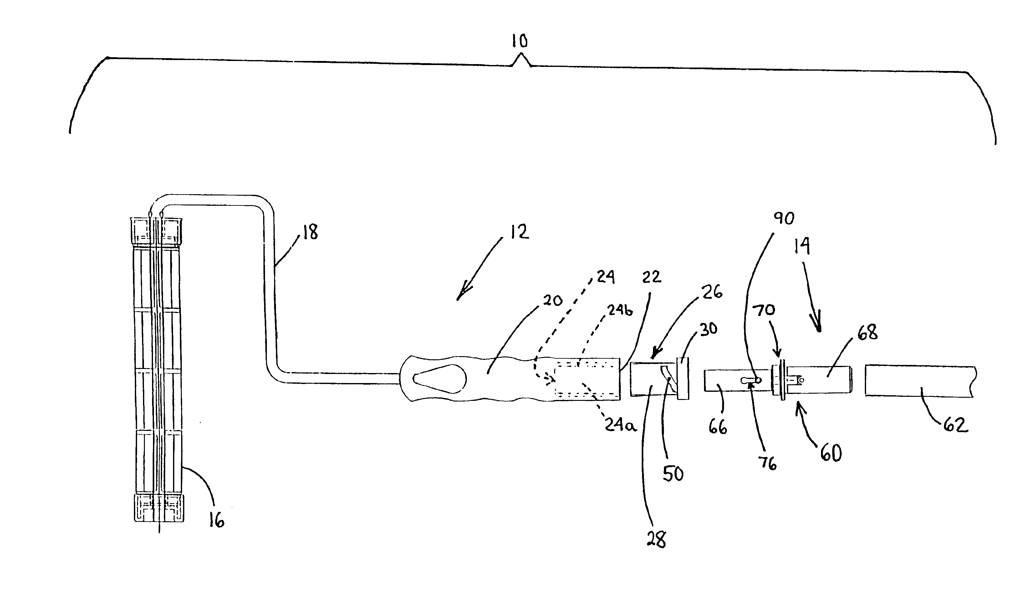
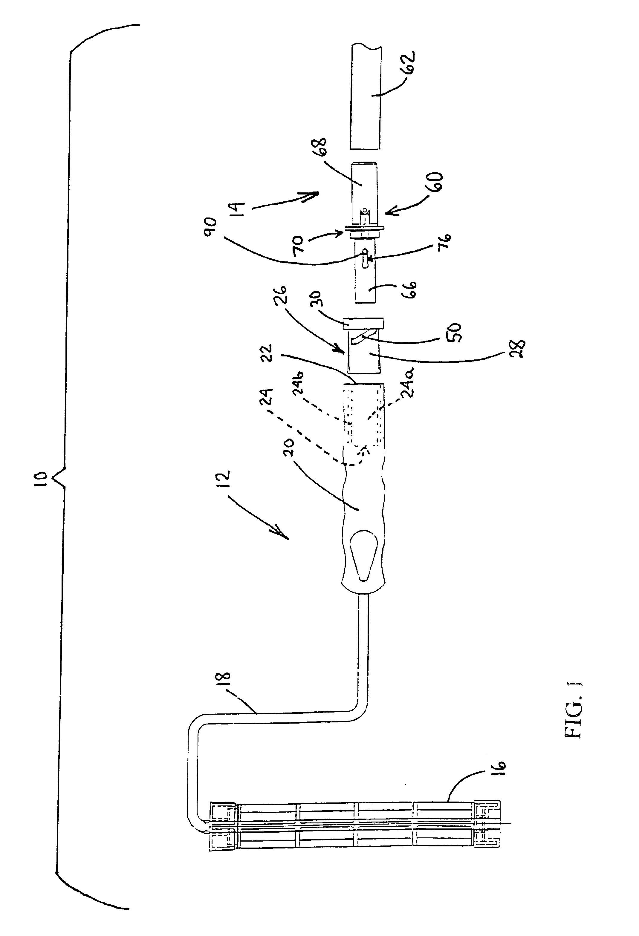
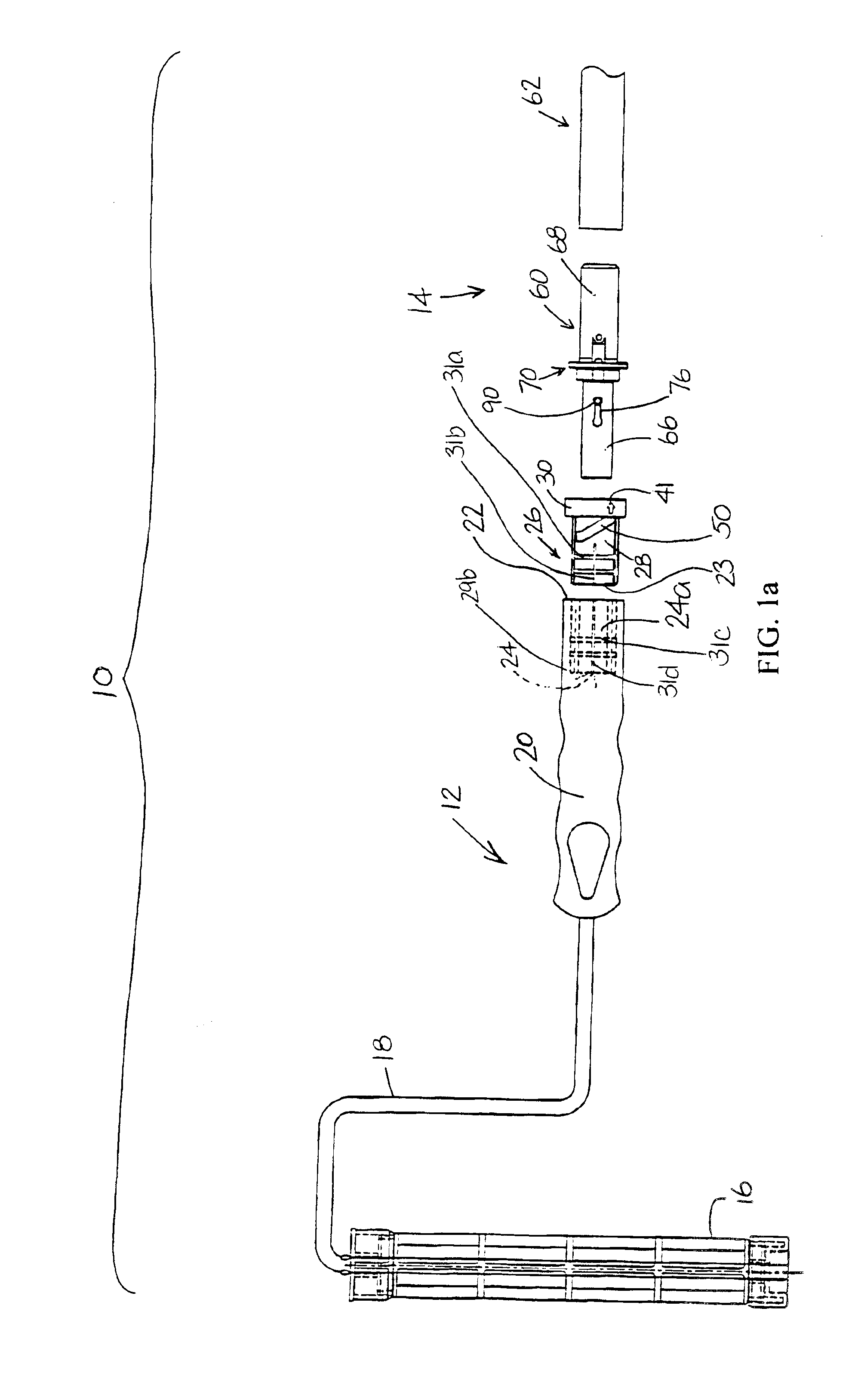
Referring now to FIG. 1, there is shown an exploded view of a portion of a tool extension assembly 10 generally comprising a tool 12, such as a paint roller, and an extension pole assembly 14.

The tool 12 includes an implement 16, such as a cylindrical cage for disposal in a paint roller cover, mounted to a wire frame 18. A lower end of the frame 18 is secured to a handle 20 having a bottom end 22. The handle 20 is composed of plastic, preferably polypropylene. An axial hole 24 (shown in phantom) extends through the bottom end 22 and into the main portion of the ha...


PUM


Abstract

A tool extension assembly including an extension pole connected to a connecting device and a tool assembly having a handle with an insert secured therein. A transversely-extending pin is movably mounted to the connecting device and is biased by a spring. The insert has a cylindrical side wall with an interior surface that defines an interior bore and interior edges that define a pair of opposing slots. The slots extend axially and circumferentially along the side wall. The connecting device is receivable in the bore of the insert such that when end portions of the pin are disposed in the slots and the handle is rotated in a first direction, the interior edges of the insert move the pin against the bias of the spring until the pin reaches end portions of the slots, at which point the pin exerts a force against the interior edges of the insert that pulls the tool assembly and the extension pole assembly together.

Description

BACKGROUND OF THE INVENTIONThe present invention relates to a tool assembly having a quick release lock mechanism for connecting a tool to an extension pole.It is often desirable to attach an extension pole to a tool, such as a paint roller, to permit an operator to use the tool in areas normally beyond the operator's reach. Conventionally, a paint roller is provided with a handle having a threaded bore extending through an end thereof. The bore is adapted to threadably receive an externally threaded end of an extension pole. One disadvantage of such a threaded connection is that during use, the paint roller may rotate so as to unscrew the extension pole from the paint roller.U.S. Pat. No. 5,288,160 to Graves et al. discloses a paint roller and extension pole assembly having a latching mechanism that addresses the foregoing disadvantage of a conventional threaded connection. The latching mechanism includes a locking lever pivotally mounted to the exterior of the extension pole and a...

Claims


Application Information

Patent Timeline
IPC IPC(8): B05C17/02B25G1/04B25G3/34B25G1/00B25G3/16B25G3/00
CPCB05C17/0205B25G1/04B25G3/16B25G3/34Y10T16/4719Y10T403/70Y10T16/473
Inventor TA, DUONG L.OLIVER, TY J.
Owner THE SHERWIN-WILLIAMS CO
Why Eureka
Try Eureka