Cylinder for spinning preparation machine

a technology of preparation machine and cylinder, which is applied in the field of cylinder for spinning preparation machine, can solve the problems of large weight of cylinder, unavoidable expensive reworking, and a long time, and achieve the effect of reducing the weight and small deviation

Inactive Publication Date: 2005-04-05
TRUETZSCHLER GMBH & CO KG
View PDF22 Cites 2 Cited by
  • Summary
  • Abstract
  • Description
  • Claims
  • Application Information

AI Technical Summary

Benefits of technology

It is an object of the invention to create a cylinder of the above-described type that avoids the aforementioned disadvantages a

Problems solved by technology

However, the known arrangement has the disadvantage that the tensioning elements create undesirable bending stresses in the projecting shaft

Method used


Image

  • Cylinder for spinning preparation machine
  • Cylinder for spinning preparation machine
  • Cylinder for spinning preparation machine

Examples


Embodiment Construction

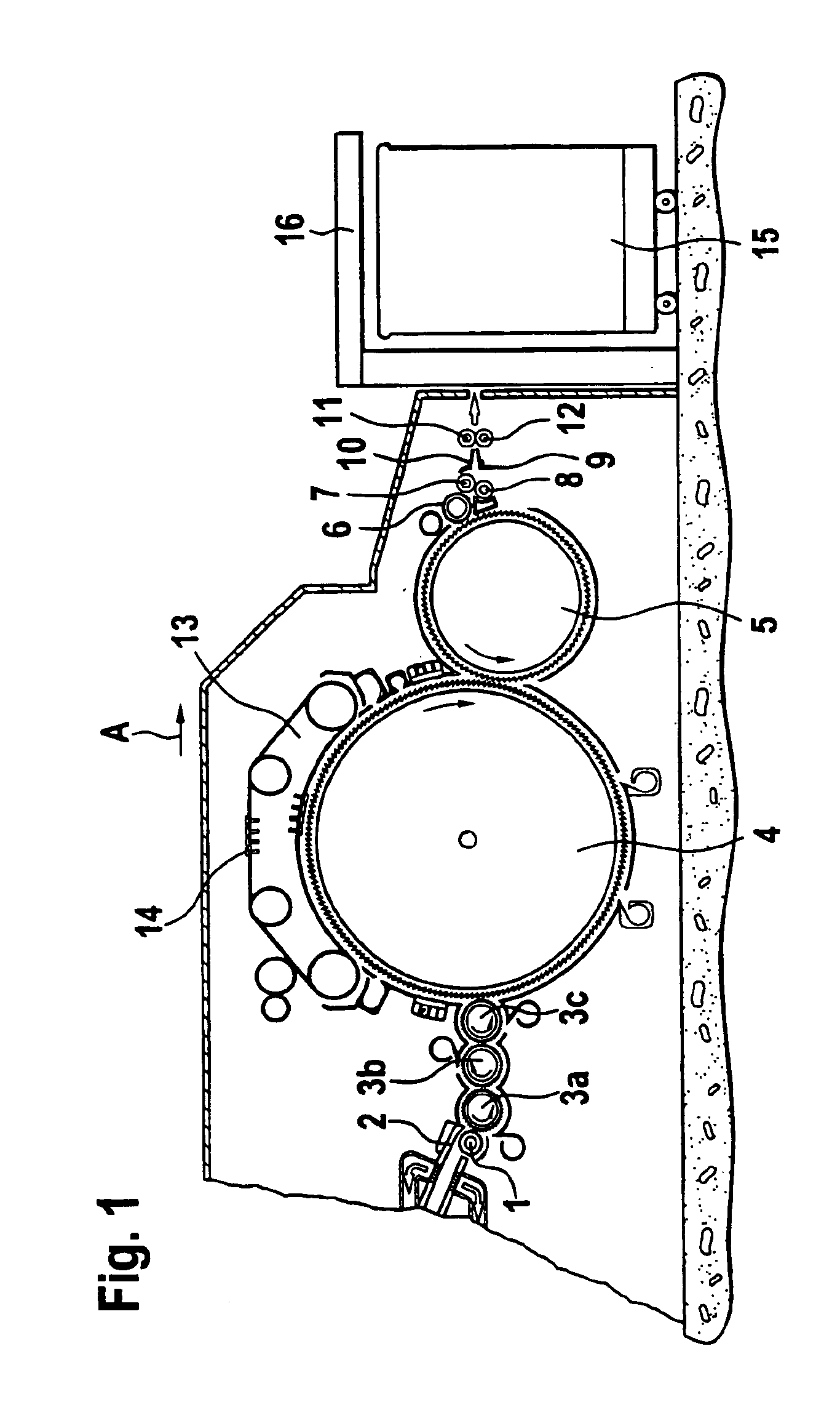
FIG. 1 shows a carding machine, for example a high-performance card DK 903 by the company Trützschler in Mönchengladbach, Germany. The carding machine has a feed roll 1, a feed table 2, licker-ins 3a, 3b, 3c, a main carding cylinder 4, a doffer 5, a stripping roll 6, crushing rolls 7, 8, a sliver guide element 9, a web trumpet 10, withdrawing rolls 11, 12, traveling flats 13 with clothed flat bars 14, a can 15 and a can holder 16. Curved arrows indicate the rotational directions of the rolls while the arrow A indicates the operating direction.

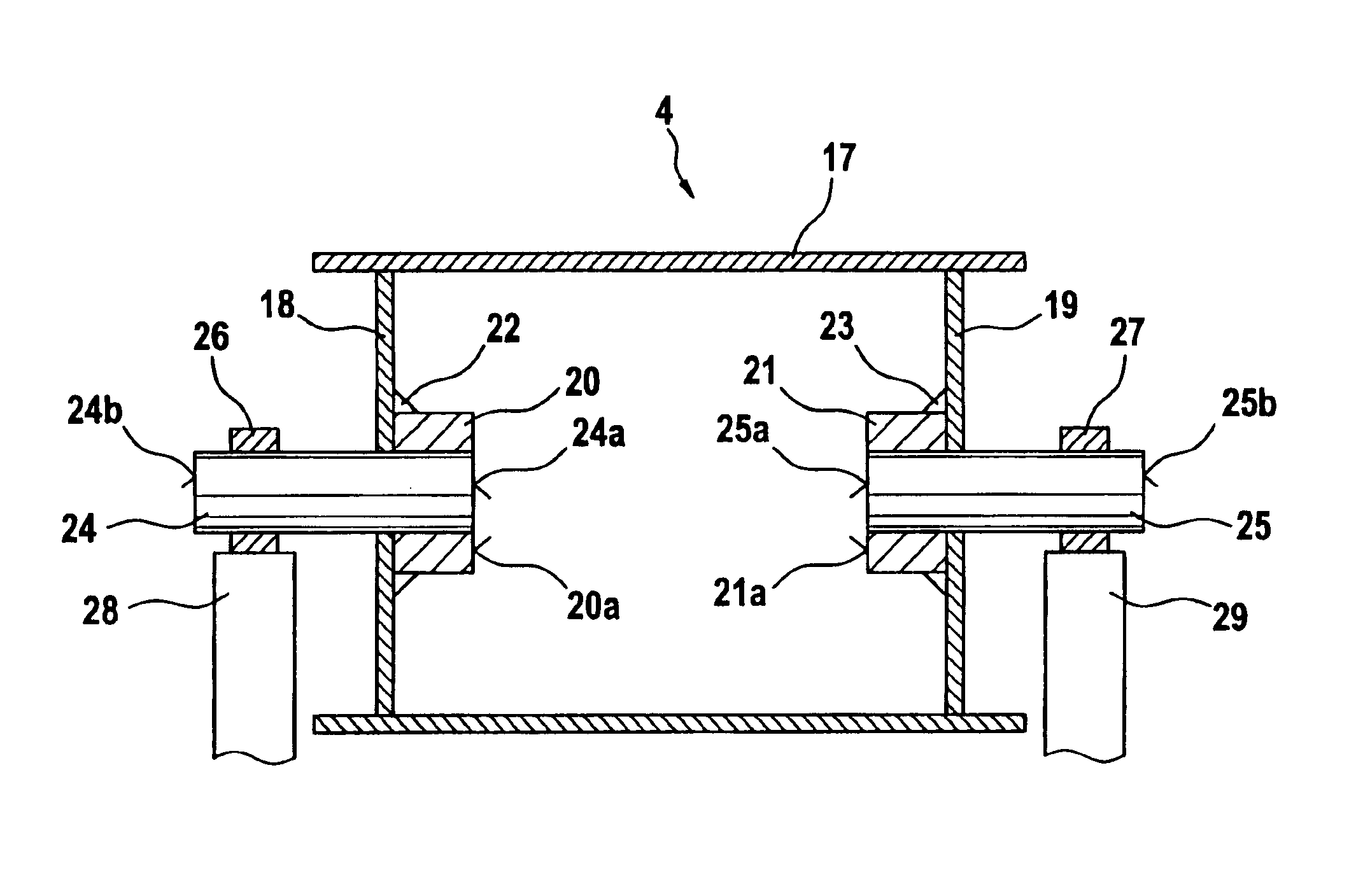
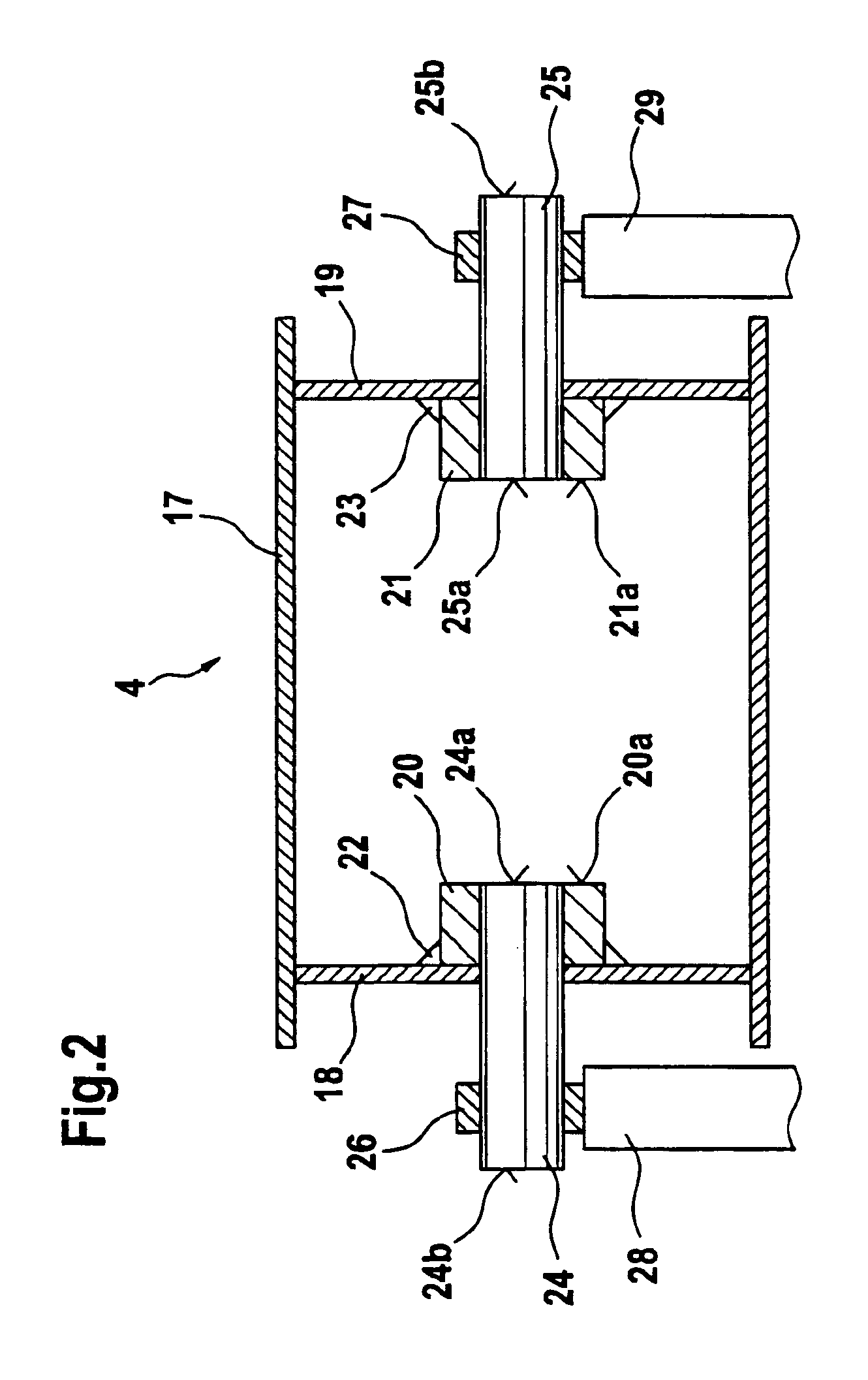
The exemplary main carding cylinder 4, shown in FIG. 2, has an outer shell 17 made of, for example, sheet steel. The outer shell 17 is respectively supported at both ends with cylinder bottoms 18 and 19 on essentially hollow-cylindrical hubs 20, 21. The hubs 20, 21 are preferably welded to the cylinder bottoms 18, 19 with welded connections 22, 23. The hub 20 is glued to a short cylindrical shaft journal 24 such that it can rotate and the hub 2...


PUM


Abstract

A cylinder is provided for a spinning preparation machine. The cylinder has an outer shell having a hub at each end of the outer shell. A separate shaft journal is connected to each hub and the shaft journals are glued to the hubs.

Description

CROSS-REFERENCE TO RELATED APPLICATIONThis application claims priority to German Patent Application No. 101 62 313.5, filed Dec. 19, 2001, the disclosure of which is incorporated herein by reference.BACKGROUND OF THE INVENTIONThe invention relates to a cylinder for a spinning preparation machine, for example a main carding cylinder, a doffer or the like on a carding machine. More particularly, the invention relates to such a cylinder where the outer shell of the cylinder at its ends rests against a hub mounted on a drive shaft.A known cylinder for a carding machine is shown in German Unexamined Published Application 35 31 850 and is provided with a continuous shaft which transfers torque by means of tensioning elements. The cylinder is accommodated by hubs that are attached to outer steel plates and is connected with tensioning elements to the drive shaft. The tensioning elements can be annular springs, for example. Once the shaft is mounted, shaft journals and the outer shell are r...

Claims


Application Information

Patent Timeline
IPC IPC(8): D01G15/16D01G15/00
CPCD01G15/16
Inventor PFERDMENGES, GERDPISCHEL, ROBERT
Owner TRUETZSCHLER GMBH & CO KG
Why Eureka
Try Eureka