Disc brake pad spreading tool

a disc brake pad and tool technology, applied in the field of disc brake pad spreading tools, can solve the problems of difficult turning of threaded rods, difficulty in replacing disc brake pads, manual effort often required to effect disc brake pad spreading, etc., and achieve the effect of improving mechanical advantages

Inactive Publication Date: 2005-04-05
LISLE CORPORATION
View PDF3 Cites 11 Cited by
  • Summary
  • Abstract
  • Description
  • Claims
  • Application Information

AI Technical Summary

Benefits of technology

Briefly, the present invention is a tool for spreading the brake pads associated with a disc brake caliper. The tool includes a plunger mounted on the end of a slidable rod which, in turn, is mounted in a hand actuated rod advancement mechanism. The rod advancement mechanism further includes a backing plate positioned in opposed relationship to the plunger. The backing plate may be fitted against a first side of a caliper brake pad assembly for a disc brake, and the plunger may then be driven into engagement with the opposite side thereby separating the disc pads and / or disc pad mounts and also simultaneously compressing the brake piston into the cylinder for the caliper. The mechanism for advancing the rod upon which the plunger is mounted comprises a fixed handle and a pivotal handle. The pivotal handle engages a feed dog that drives the rod incrementally forward with each reciprocal movement of the pivotal handle. A rod brake or pawl comprised of a second pivotal plate is provided for engaging the drive rod and precluding backwards movement of the rod. In other words, as the rod is moved forward in incremental steps, the rod braking plate maintains the rod in a desired or fixed advanced position. With the combination of the invention, an improved mechanical advantage is achieved for driving the pads of the disc brake apart and for driving the piston associated with the disc brake caliper into the housing of the caliper. In this manner, new pads may be placed upon pad mounts in the caliper and properly spaced so as to permit the caliper to be reassembled with the disc brake assembly.

Problems solved by technology

From time to time, it is necessary to replace the pads due to the fact that they wear from frictional contact with the rotating disc.
A difficulty associated with such a construction, however, is the manual effort often required to effect spreading the disc brake pads.
That is, turning the threaded rod may be difficult because the brake piston which drives the pads together may be difficult to reposition or move, and because it impinges against one of the pads, pad separation will be difficult.

Method used


Image

  • Disc brake pad spreading tool
  • Disc brake pad spreading tool
  • Disc brake pad spreading tool

Examples


Embodiment Construction

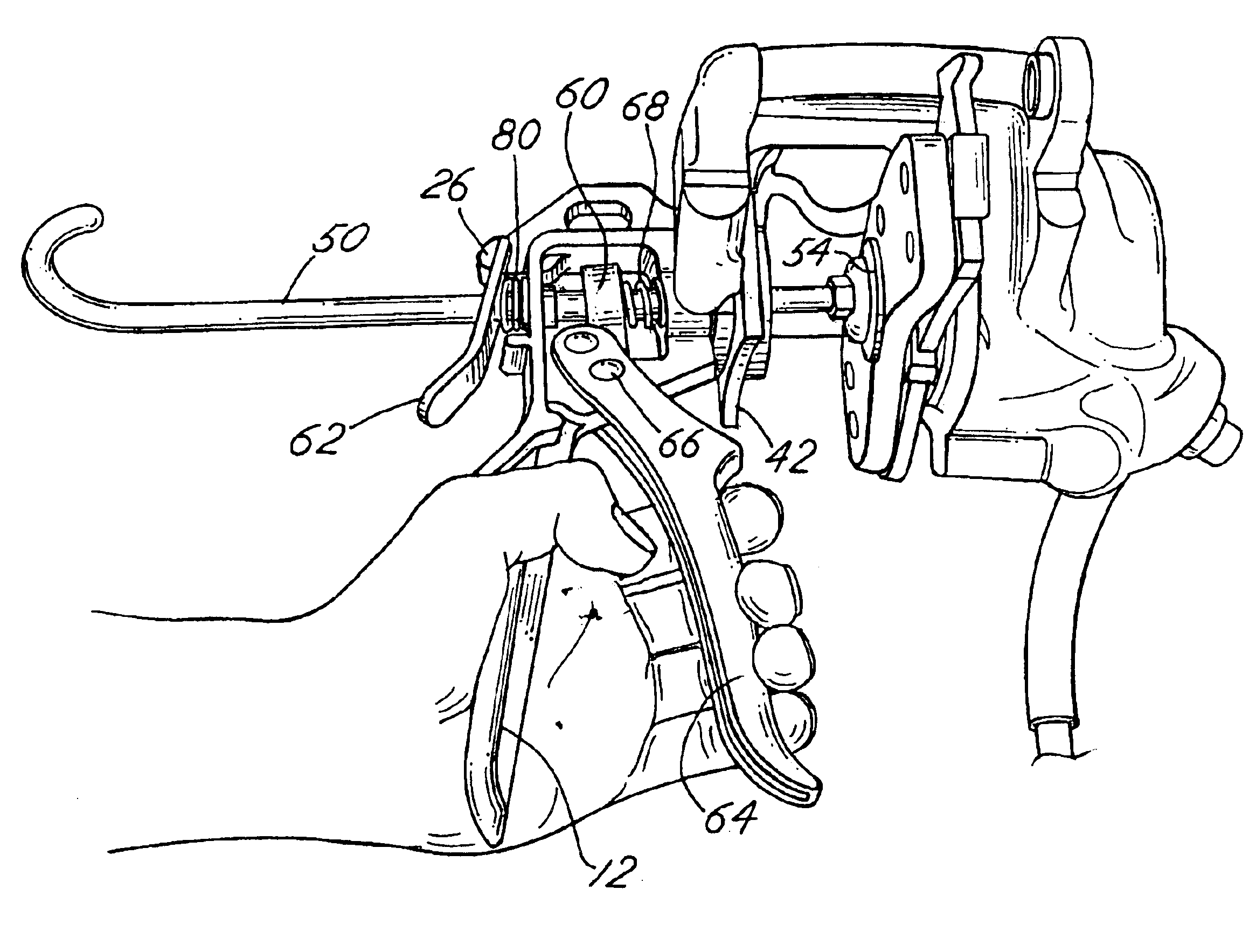
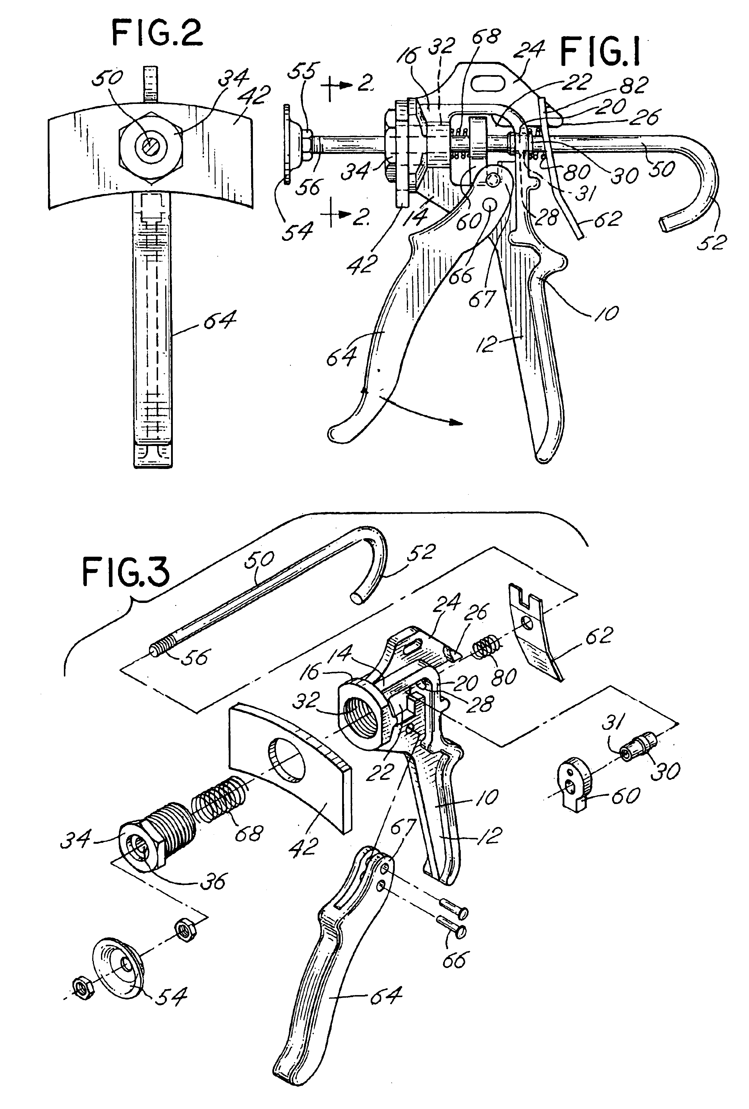
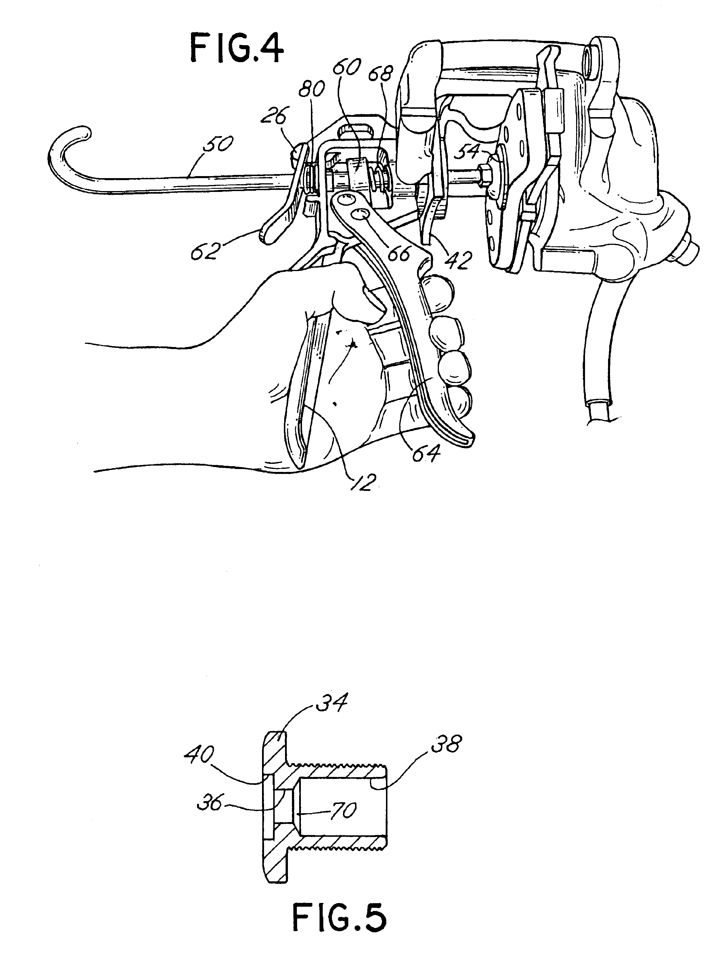
Referring to the figures, the tool of the invention comprises a body or frame member 10. The frame member 10 includes a depending fixed handle 12 with an upper frame element 14 comprising a first or forward frame section 16 and a second or rear frame section 20. The frame sections 16 and 20 are generally parallel to one another and spaced to define a window 22. A reinforcing rib 24 with a mounting projection 26 is provided on the top of the frame element 14. The rear frame section 20 includes a throughbore 28 into which a cylindrical hollow fitting 30 with throughbore 31 is inserted. The front frame section 16 also includes a throughbore 32 into which a flanged nut 34 having an internal throughbore 36 with counterbore 38 on the inside end and counterbore 40 on the outside end being provided. The flanged nut 34 is threaded into the front frame section 16 and holds a backing plate 42 onto the front frame section 16. The backing plate is a planar plate having a generally arcuate shape ...


PUM

PropertyMeasurementUnit
mechanical advantageaaaaaaaaaa
shapeaaaaaaaaaa
biasing forceaaaaaaaaaa

Abstract

A tool for spreading brake pads and for compressing the piston of a disc brake assembly of the type including a disc brake caliper housing for the pads and piston. The tool includes manually operated handles which drive a rod attached to a plunger that engages one of the disc brake pads. The housing for the tool includes a backing plate which is engaged against the caliper pad. The backing plate and plunger are driven in a manner which causes them to become spaced from one another. A mechanical advantage is achieved by utilization of handles with a lever arm extension associated with a pivotal handle.

Description

BACKGROUND OF THE INVENTIONIn a principal aspect the present invention relates to a tool for spreading the disc pads of a vehicle disc brake assembly so that the pads may be replaced. The invention thus comprises a manually actuated disc pad spreading tool.In the repair of vehicles and, for example, with respect to the repair of vehicle braking systems, many special tools are desirable. Disc brakes typically include a caliper housing which is mounted adjacent a wheel. The housing includes opposed disc pads for clamping a disc associated with a wheel of the vehicle. From time to time, it is necessary to replace the pads due to the fact that they wear from frictional contact with the rotating disc. In such circumstances, the caliper housing is typically removed from the wheel assembly of the vehicle, and the disc pads are caused to be spread. The spread pads may then be easily removed and replaced. The caliper housing may then be replaced in the wheel assembly positioned for engagemen...

Claims


Application Information

Patent Timeline
Patent Type & Authority Patents(United States)
IPC IPC(8): B25B27/00
CPCB25B27/0035F16D65/0043Y10T29/53683
Inventor PLOEGER, RANDALL J.JULIANO, GEORGE P.JULIANO, MARTHA
Owner LISLE CORPORATION
Why Eureka
Try Eureka