
Plow system for a vehicle

Inactive Publication Date: 2005-04-05
COVENANT RESOLUTIONS
View PDF44 Cites 48 Cited by
  • Summary
  • Abstract
  • Description
  • Claims
  • Application Information

AI Technical Summary

Benefits of technology

In one embodiment, the attachment system comprises a plurality of fasteners that extend through at least one of the at least one rib and the plurality of channels, to, in turn, releasably retain the blade thereto. In another such embodiment, the attachment system further comprises an insulator positioned between the frame assembly and the blade, to, in turn, substantially preclude any galvanic corrosion therebetween.
In one such embodiment, the at least one frame attachment member comprises a frame attachment member positioned proximate either end of the body. Additionally, the at least one frame receiver member comprises a frame receiver member positioned proximate either end of the body and proximate the frame attachment members. Preferably, each frame attachment member further comprises at least two flanges capable of securing to a different surface of a frame of a vehicle. Likewise, it is preferred that the frame of the rear snow plow assembly further includes at least one guide. The at least one frame receiver member further includes at least one channel. The at least one guide is capable of receipt within the at least one channel, to, in turn, further facilitate releasable engagement of the rear snow plow assembly with the hitch.
In one embodiment, the frame further comprises a body, at least one upper linkage and at least one lower linkage. The at least one upper linkage is pivotally associated with each of the blade and the body. The at least one lower linkage is pivotally associated with each of the blade and the body. The upper and lower linkages are substantially parallel in orientation, to, in turn, facilitate linear movement of the blade relative to the body.

Problems solved by technology

While the technology associated with plows has evolved over the years, certain lingering problems have not been resolved, and certain new problems have been presented.
For example, the environment in which snow plows operate is extremely harsh.
Blades are typically made out of a mild steel, which is highly susceptible to rust and abrasive damage.
While these blades are typically painted to protect the underlying steel, the paint is quickly abraded and, in turn, the bare steel is exposed to the elements.
Destructive corrosion soon follows.
However, while corrosion is not an issue with such composites, such materials do not respond well to the abrasive environment in which the snow plow operates.
Furthermore, the composites tend to be exceedingly expensive and difficult to manufacture.
Other materials do not respond well in such a harsh and abrasive environment.
Moreover, snow plows of the type described above are generally quite heavy.
As a result, repetitive operation of trucks with heavy snow plows has lead to failures in the frames.
In addition, the large weight of the plows has placed an additional toll on brakes, transmissions, engines and suspension, causing premature failure and replacement of same.
Furthermore, the heavy plows have an adverse effect on fuel economy and emissions.

Method used


Image

  • Plow system for a vehicle
  • Plow system for a vehicle
  • Plow system for a vehicle

Examples


Embodiment Construction

While this invention is capable of embodiment in many different forms, there is shown in the drawings and will be described herein in detail, one specific embodiment with the understanding that the present disclosure is to be considered as an exemplification of the principles of the invention and is not intended to limit the invention to the embodiment illustrated.

It will be understood that like or analogous elements and / or components, referred to herein, are identified throughout the drawings by like reference characters. In addition, it will be understood that the drawings are merely representations, and some of the components may have been distorted from actual scale for purposes of pictorial clarity.

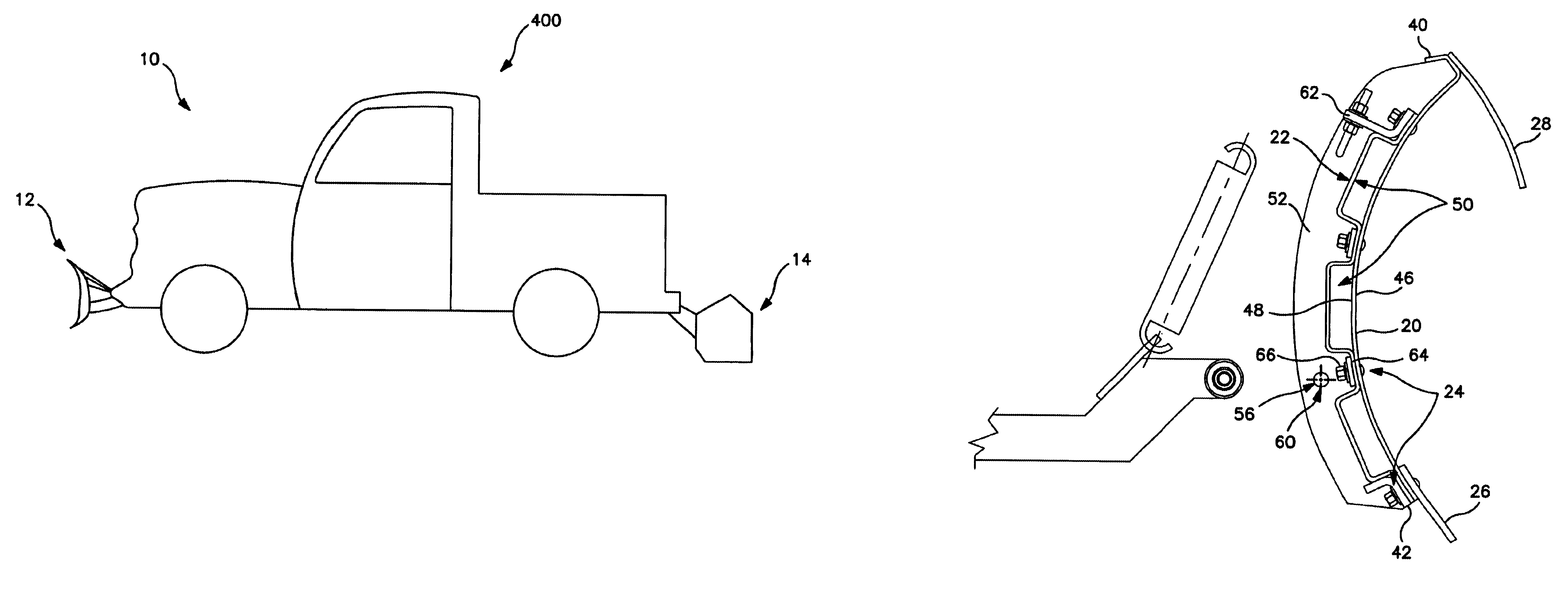
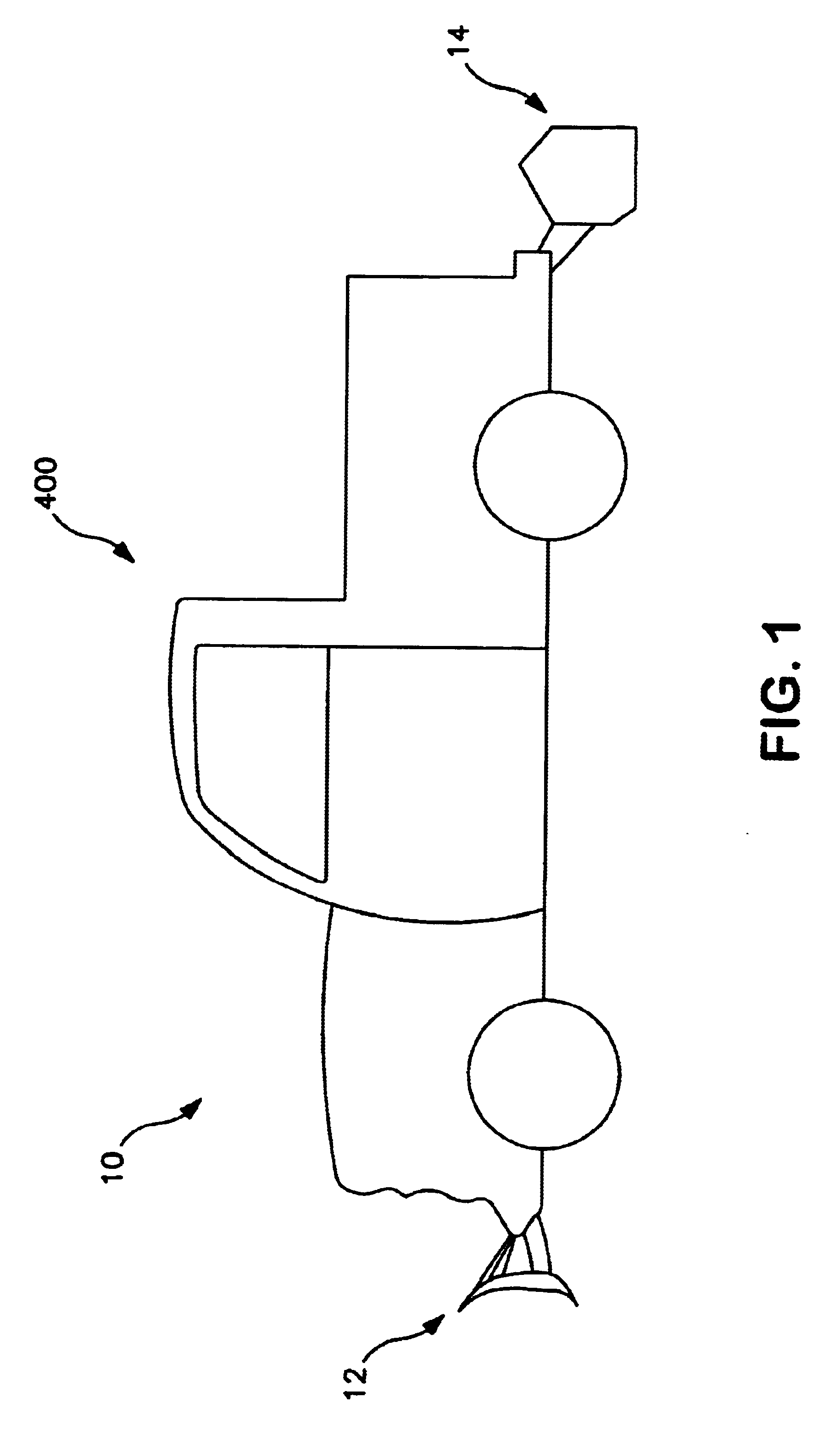
Snow plow system 10 is shown in FIG. 1 as comprising front snow plow assembly 12 and rear snow plow assembly 14. The snow plow system is configured for use in association with vehicle 400, such as a quarter ton, half ton and three quarter ton pick-up truck conventionally provided by ...


PUM


Abstract

The invention comprises a snow plow system capable of attachment to a vehicle. The snow plow system comprises a front snow plow assembly and a rear snow plow assembly. The front snow plow assembly includes a blade, a frame assembly and an attachment system. The attachment system is capable of attaching the blade to the frame assembly. The rear snow plow assembly includes a frame and a blade attached. The frame of the front snow plow assembly and the frame of the rear snow plow assembly comprise an aluminum material having a temper of at least T4.

Description

BACKGROUND OF THE INVENTION1. Field of the InventionThe invention relates in general to a plow, and more particularly, to a plow system for use in association with a vehicle, such as a pick-up truck, to, in turn, facilitate the removal of, for example, ice, snow and sleet from a roadway.2. Background ArtVehicle plows have been known in the art for many years, to, for example, remove snow from an outside surface. While the technology associated with plows has evolved over the years, certain lingering problems have not been resolved, and certain new problems have been presented.For example, the environment in which snow plows operate is extremely harsh. The blade of the plow is constantly abraded by snow and ice, as well as the underlying gravel or paved surface. Blades are typically made out of a mild steel, which is highly susceptible to rust and abrasive damage. While these blades are typically painted to protect the underlying steel, the paint is quickly abraded and, in turn, the ...

Claims


Application Information

Patent Timeline
IPC IPC(8): E01H5/06E01H5/04
CPCE01H5/06E01H5/068E01H5/066
Inventor MULLETT, DONALD EDWARD
Owner COVENANT RESOLUTIONS
Learn More