Piston rod-less linear drive

a technology of linear drive and piston rod, which is applied in the direction of fluid-pressure actuators, machines/engines, mechanical equipment, etc., can solve the problems of increasing wear liability

Inactive Publication Date: 2005-04-05
FESTO AG & CO KG
View PDF8 Cites 5 Cited by
  • Summary
  • Abstract
  • Description
  • Claims
  • Application Information

AI Technical Summary

Benefits of technology

The distribution of forces in the case of the transmission of the drive force from the drive part to the guide slide thus does not take place directly between the entraining member and the guide slide but indirectly and by way of the separate abutment means placed between the entraining member and the guide slide. Cooperating with counter abutments on the housing this abutment means serves to limit the setting path of the guide slide, which is able to be moved in relation to the housing, and assumes a double function, since it additionally functions as a force transmitting means between the entraining member and the guide slide. Assembly of the linear drive is accordingly substantially simplified, because the relative adjustment between the entraining member and the guide slide on the one hand and on the other hand the correct positioning on the guide slide of the abutment means may take place in a single working operation and taking into account interacting features. Moreover, using such a design leads to a relatively simple structure with a small number of components.
It is an advantage if, respectively in the direction of the impact force acting on them, the two abutment units are respectively supported on a counter abutment in an interlocking or positively fitting manner and not merely frictionally on the guide slide. Accordingly, the entraining member and therefore also the drive part connected with the entraining member for the transmission of force, is decoupled from the impact forces, something which has a favorable effect on the working life. Moreover, it is possible to ensure that even on the occasion of a violent impact there will be no change in the relative position between the abutment face provided on the abutment unit and the guide slide.
If the entraining member is only attached to one abutment unit, the two abutment units will be conveniently fixedly joined together after making the desired adjustment so that between them in the finally installed state the transmission of force will be possible in the longitudinal direction of the housing. This ensures that the relative position between the entraining member and the guide slide will not be changed in the longitudinal direction of the housing even if between these two components there is a substantial transmission of force owing to high acceleration force and / or to heavy loads to be shifted. The connection between the two abutment units preferably takes place by a joint such as a bonded or welded joint.
The attachment of the entraining member to only one abutment unit is to be recommended in the case of linear drives with a small overall size. More particularly in the case of large overall sizes a simultaneous attachment of the entraining member to both abutment units is preferred. In this connection the two abutment units will respectively possess an abutment part provided to cooperate with an counter abutment and a holding part provided for attachment of the entraining member, the two parts of a respective abutment unit being adjustable in the longitudinal direction of the housing in relation to one another during assembly so that an independent adjustment of the abutment part and of the holding part of the respective abutment unit is possible. Accordingly there is a high degree of adaptability as regards the attachment of the entraining member, an adjustment here not affecting the positioning of the abutment parts.
The linear drive may be in the form of an electrically operated design and for example have a lead screw drive, which as a drive part is able to be shifted and is in the form of a lead screw nut. However a particularly advantageous design is one in which the drive part is in the form of a piston and the actuating force is produced by fluid power. In such a case the longitudinal slot is provided with a band-like sealing means to prevent uncontrolled loss of fluid through the longitudinal slot.

Problems solved by technology

This direct and permanent screw attachment may lead to strains in the system which increase liability to wear.

Method used


Image

  • Piston rod-less linear drive
  • Piston rod-less linear drive
  • Piston rod-less linear drive

Examples


Embodiment Construction

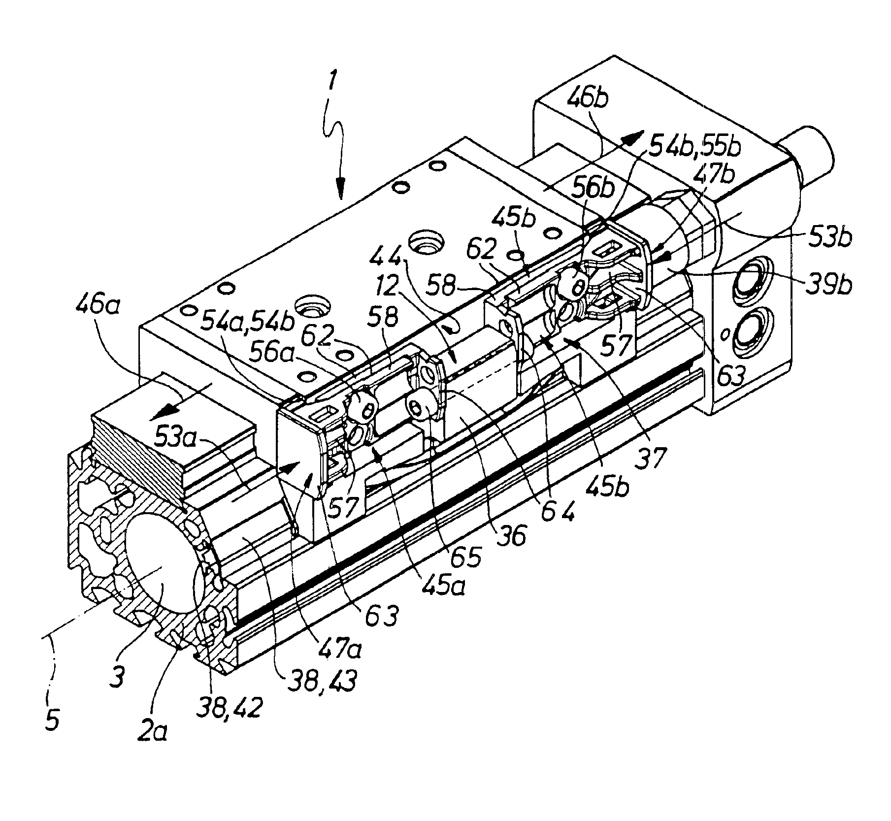
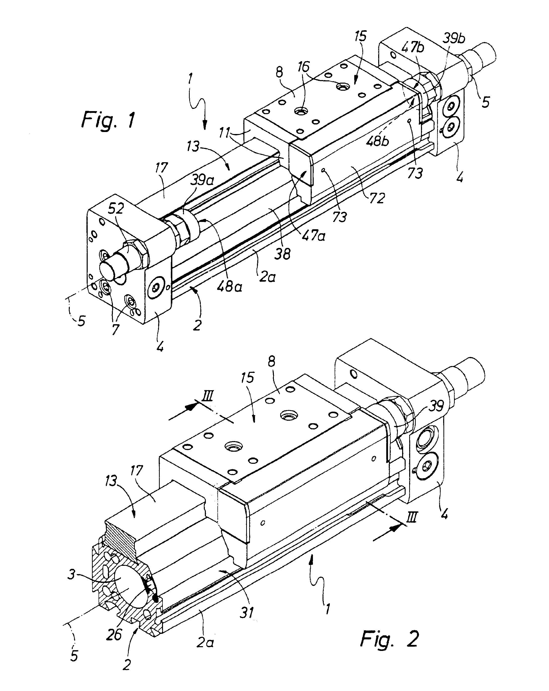
The first working example possesses a piston rod-less linear drive generally referenced 1 and in a design suitable for fluid power operation. It is more especially designed for operation by compressed air.

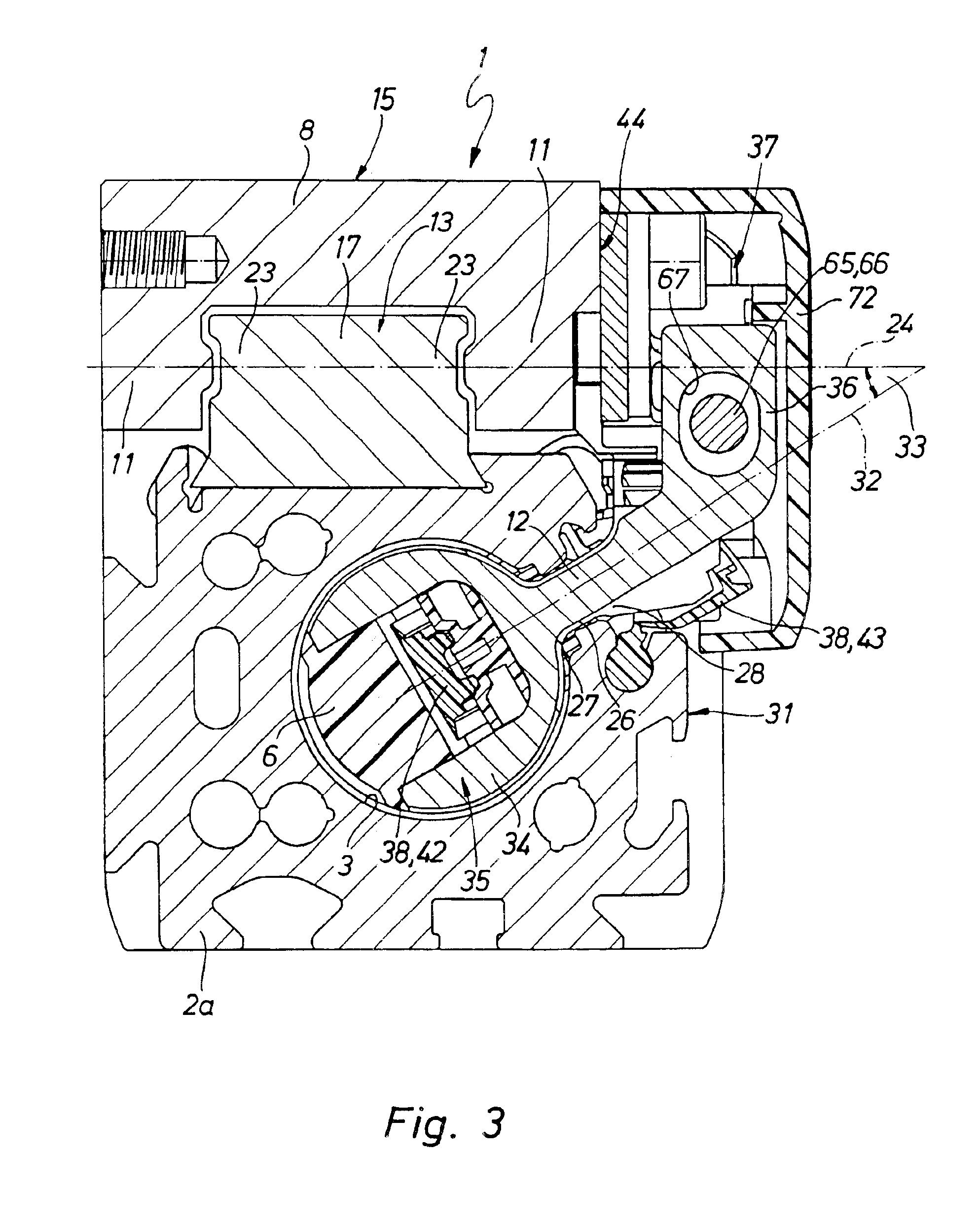
The linear drive has an longitudinal housing 2 with a housing tube 2a defining in its interior a preferably cylindrical receiving space, said tube 2a having respective cover plates 4 at its ends.

In the interior of the receiving space 3 there is a drive part 6 able to be moved in the longitudinal direction 5 of the housing, indicated in chained lines, such drive part being in the form of a piston which divides the receiving space 3 into two axially sequential working chambers in a fluid-tight manner. By way of connection ports 7, which in the working example are jointly provided on a single end plate 4, it is possible for the supply and removal of pressure medium to take place to and from the working spaces. Thus the drive part 6 may be caused to perform a drive movement in the long...


PUM


Abstract

A piston rod-less linear drive has an elongated housing containing a guide slide moving in the longitudinal direction. The connection between the entraining member and the guide slide is with the interposition of an abutment unit attached to the guide slide, such abutment unit furthermore serving to limit the path of movement of the guide slide.

Description

BACKGROUND OF THE INVENTIONThe invention relates to a piston rod-less linear drive comprising an elongated housing defining a receiving space for a drive part able to be moved in the longitudinal direction of the housing, such drive part being kinematically coupled by way of a entraining member, extending through a longitudinal slot in the housing, with a guide slide, which runs in the longitudinal direction of the housing on a linear guide attached to the housing.THE PRIOR ARTIn the case of a linear drive of this type disclosed in the European patent publication 1,182,359 A1 the entraining member has its outer end section fitting in a recess facing away from the guide slide and is permanently screwed to the guide slide directly. This direct and permanent screw attachment may lead to strains in the system which increase liability to wear. In order to limit the path of movement the guide slide can at its end cooperate with the end plates of the housing.SHORT SUMMARY OF THE INVENTIONO...

Claims


Application Information

Patent Timeline
Patent Type & Authority Patents(United States)
IPC IPC(8): F15B15/00F15B15/24F15B15/08
CPCF15B15/24F15B15/082
Inventor DOLESCHEL, BERNDWEBER, MARKUS
Owner FESTO AG & CO KG
Why Eureka
Try Eureka