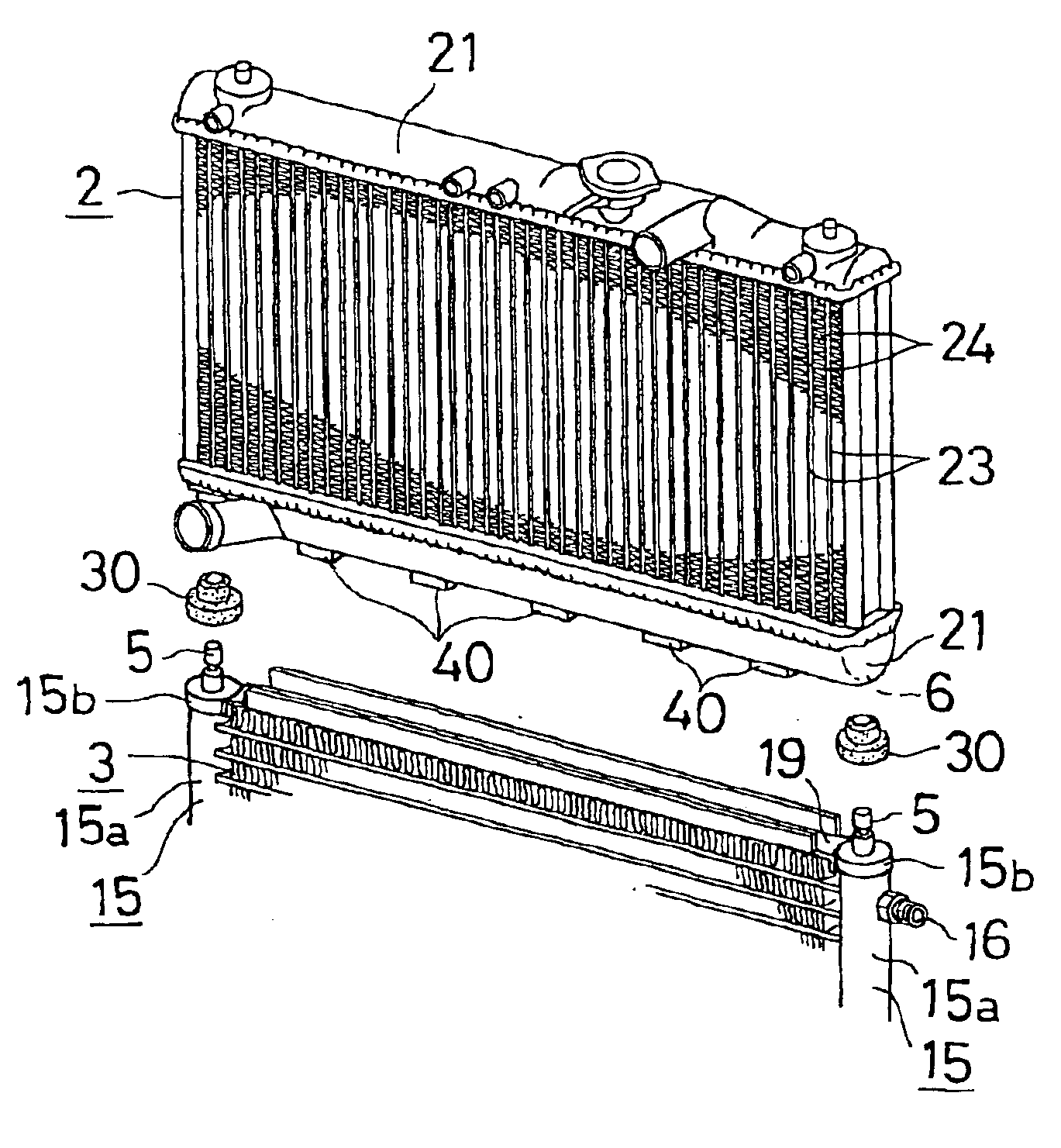
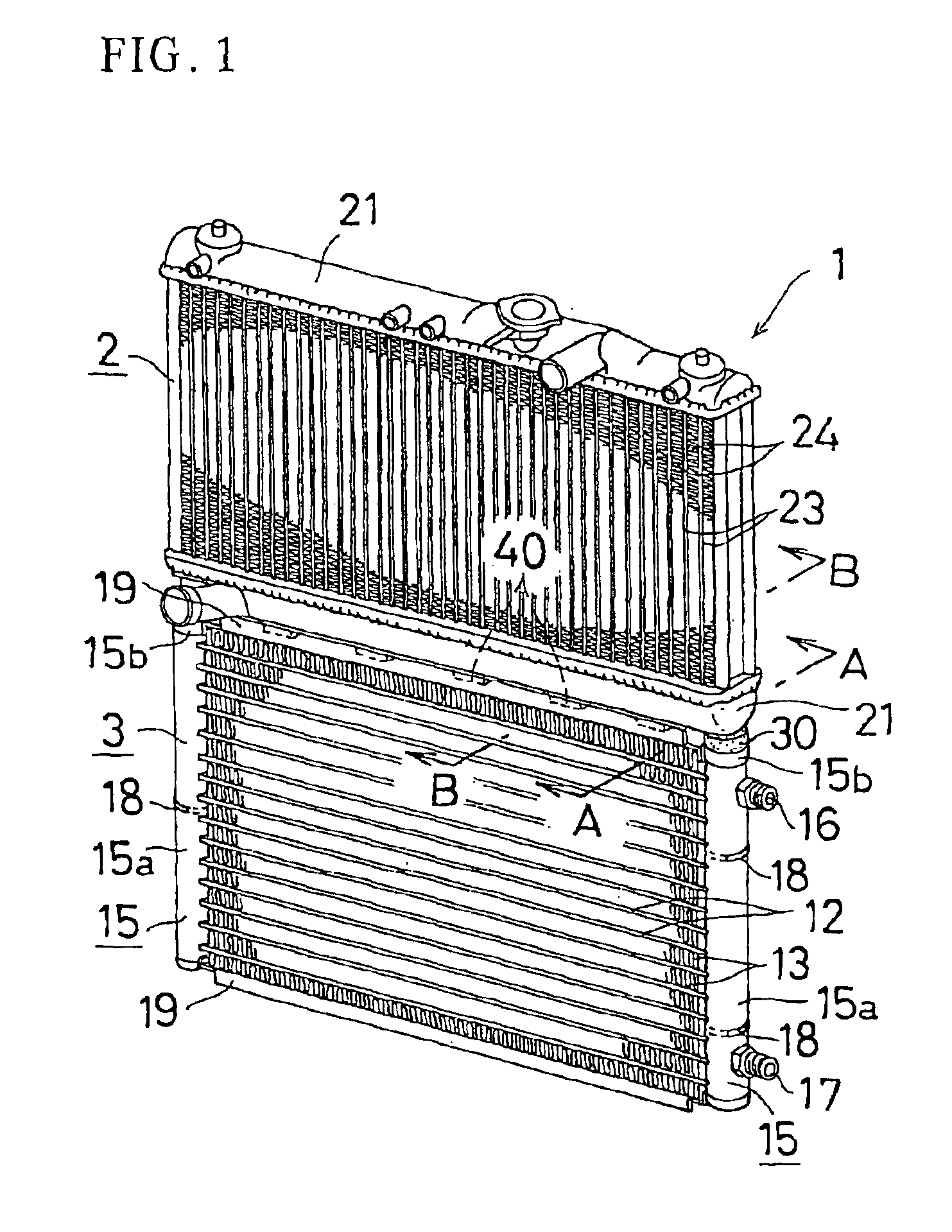
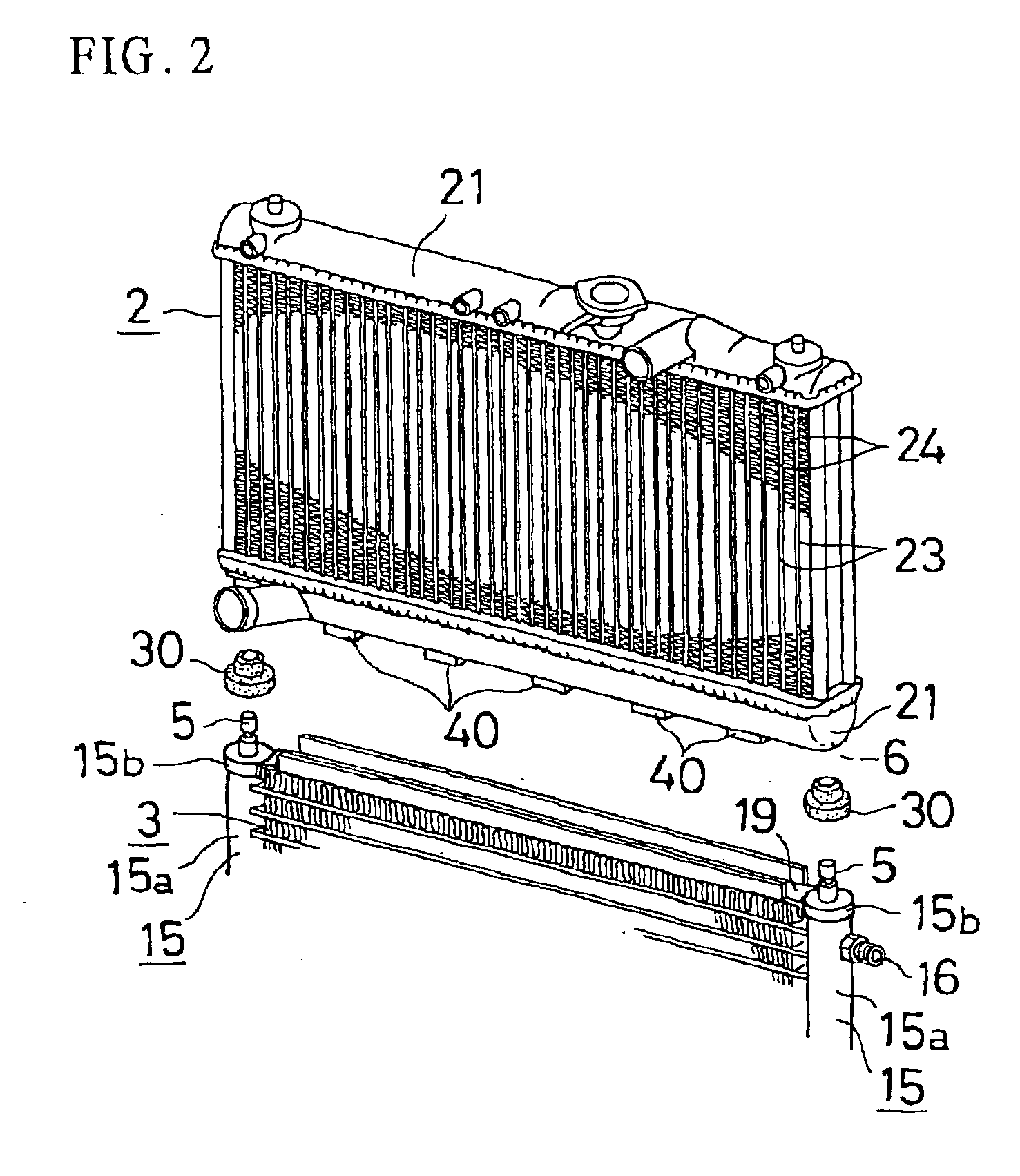
In the aforementioned integrated heat exchanger, the integration of the first and second heat exchangers 2 and 3 can be performed by providing the fitting protruded portion 5 on one of the bottom surface of the first heat exchanger 2 and the upper surface of the second heat exchanger 3 and the fitting dented portion 6 on the other thereof almost without changing the existing structure of the first and second heat exchangers 2 and 3. Therefore, almost no new investment for manufacturing equipment is required, resulting in a low manufacturing cost. Furthermore, since the first and second heat exchangers 2 and 3 do not share a header as in the aforementioned conventional heat exchanger but are separately manufactured and then integrally connected with each other, the manufacturing and / or replacing work can be performed easily without increasing the manufacturing and / or replacing steps. Furthermore, since the first heat exchanger 2 is connected to the upper portion of the second heat exchanger 3, in cases where the first heat exchanger 2 is a radiator, the cooling-water can be smoothly supplied to the radiator 2. Since the first and second heat exchangers 2 and 3 are not juxtaposed so as to form two rows but disposed one on the other so as to form a
single row, the thickness can be reduced, resulting in reduced air-pressure loss as a whole heat exchanger, which in turn results in a high-performance heat exchanger.
It is preferable that the fitting protruded portion 5 is fitted in the fitting dented portion 6 via a buffer member 30 made of elastic material. Even in cases where there are some dimensional errors in the first and second heat exchangers 2 and 3, since the buffer member 30 can absorb such errors, the first and second heat exchangers 2 and 3 can be integrally connected with each other without difficulty. Furthermore, even if the heat exchangers vibrate, due to the existence of the buffer member 30, the first and second heat exchangers 2 and 3 will not be interfered each other, resulting in enhanced resistance to vibration.
It is preferable that at least one downwardly protruded protrusion 40 is provided at the bottom surface of the first heat exchanger 2, wherein a channel member 19 having a generally U-shaped cross-section is provided at the upper surface of the second heat exchanger 3 so as to extend along a widthwise direction thereof, and wherein the protrusion 40 is fitted in the channel member 19, whereby the first and second heat exchangers 2 and 3 are connected with each other and almost no gap or no gap is formed between the first and second heat exchangers 2 and 3 by the channel member 19 to prevent air passage therebetween. In this case, the first and second heat exchangers 2 and 3 can be connected more firmly with each other, and the cooling performance will be further improved by the prevention of air passage between the first and second heat exchangers 2 and 3.
It is also preferable that the first heat exchanger 2 includes a pair of horizontally disposed upper and lower tank portions 21 and 21 and a plurality of tubes 23 connecting the upper and lower tank portions 21 and 21, wherein the second heat exchanger 3 includes a pair of vertically disposed right and left headers 15 and 15 and a plurality of tubes 12 connecting the right and left headers 15 and 15, wherein a left-hand side fitting protruded portion 5 is provided at one of a bottom surface of a left end portion of the lower tank portion 21 of the first heat exchanger 2 and an upper portion of the left header 13, and a left-hand side fitting dented portion 6 is provided at the other thereof, wherein a right-hand side fitting protruded portion 5 is provided at one of a bottom surface of a right end portion of the lower tank portion 21 of the first heat exchanger 2 and an upper end portion of the right header 15 of the second heat exchanger 3, and a right-hand side fitting dented portion 6 is provided at the other thereof, and wherein the left-hand side fitting protruded portion 5 is fitted in the left-hand side fitting dented portion 6 and the right-hand side fitting protruded portion 5 is fitted in the right-hand side fitting dented portion 6, whereby the first heat exchanger 2 is integrally connected to an upper portion of the second heat exchanger 3. In this case, the connection of the first and second heat exchangers 2 and 3 can be performed easily and both the heat exchangers can be integrally connected with each other more stably.
It is also preferable that the fitting dented portions 6 and 6 are provided at the bottom surfaces of right and left end portions of the lower tank portion 21 of the first heat exchanger 2, and the fitting protruded portions 5 and 5 are provided at upper ends of the right and left headers 15 and 15 of the second heat exchanger 3. According to this structure, the gap between the first and second heat exchangers 2 and 3 can be further decreased, and the weight as a whole heat exchanger can be further reduced. In cases where the tank portion 21 of the first heat exchanger 2 is made of resin, since the fitting dented portion 6 can be simultaneously formed at the time of molding the tank portion 21, the productivity can be improved and the manufacturing cost can be further reduced. Furthermore, since the fitting protruded portions 5 and 5 are just added to the second heat exchanger 3, the structure of the second heat exchanger 3 can be kept simple in structure, resulting in enhanced productivity and a reduced manufacturing cost.

