Device for disinfecting door handles

Inactive Publication Date: 2005-04-05
CALLUENG RONEL DOMINGO
View PDF15 Cites 55 Cited by
  • Summary
  • Abstract
  • Description
  • Claims
  • Application Information

AI Technical Summary

Benefits of technology

g) a controller effective to activate and deactivate the pump.
There is also provided an improved method for disinfecting door handles and knobs comprising the steps of:
(I) providing a device comprising a) a vessel containing a liquid comprising soap or disinfectant material, b) a handle operation sensor effective to detect whether a human hand is currently operating the handle, c) a nozzle adapted to form an aeroso

Problems solved by technology

Indeed in public bathrooms the problem is particularly severe because these facilities are designed to dispose of large volumes of human waste, which contains up to 30% bacteria.
However the benefits of hand w

Method used


Image

  • Device for disinfecting door handles
  • Device for disinfecting door handles
  • Device for disinfecting door handles

Examples


Embodiment Construction

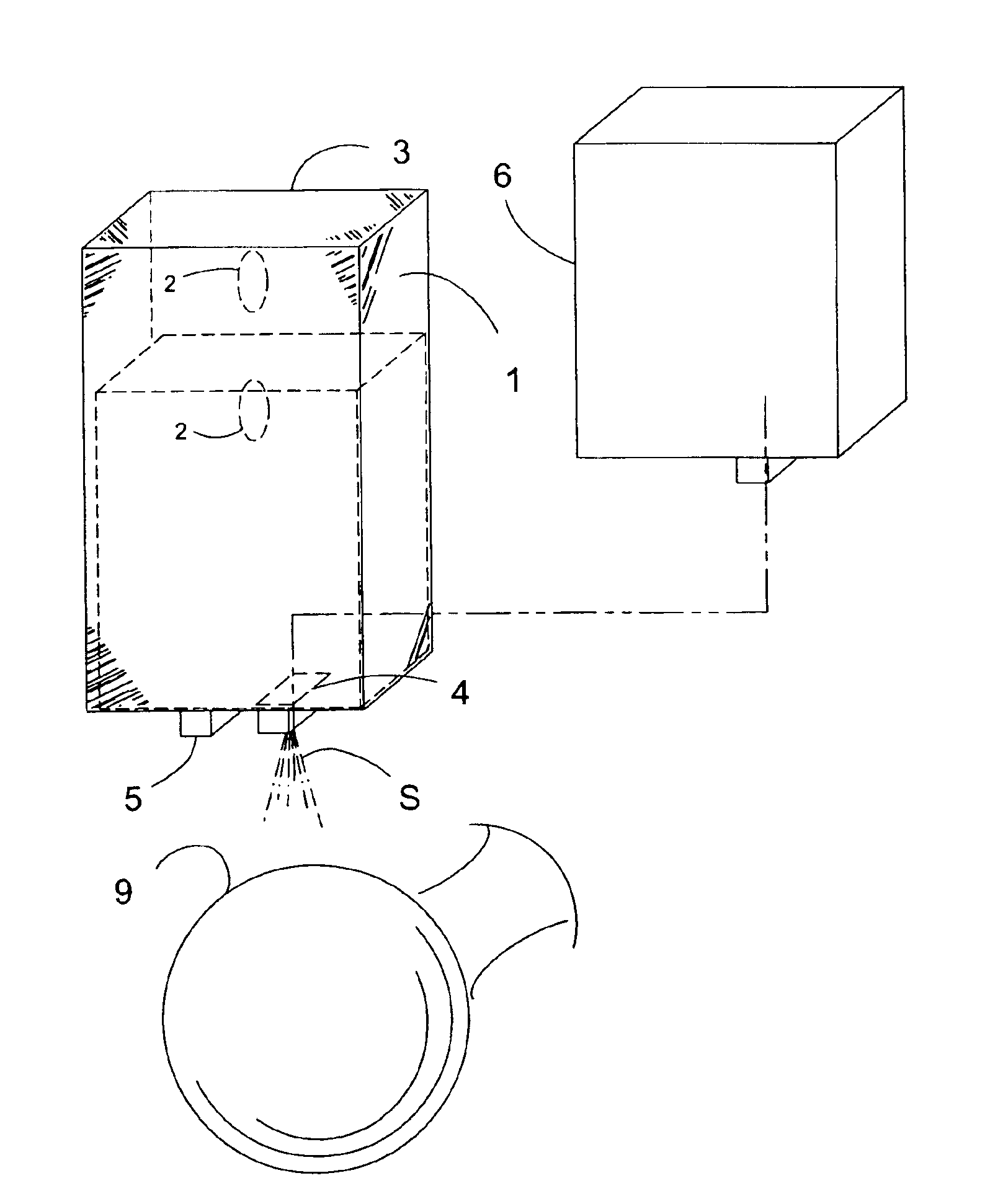
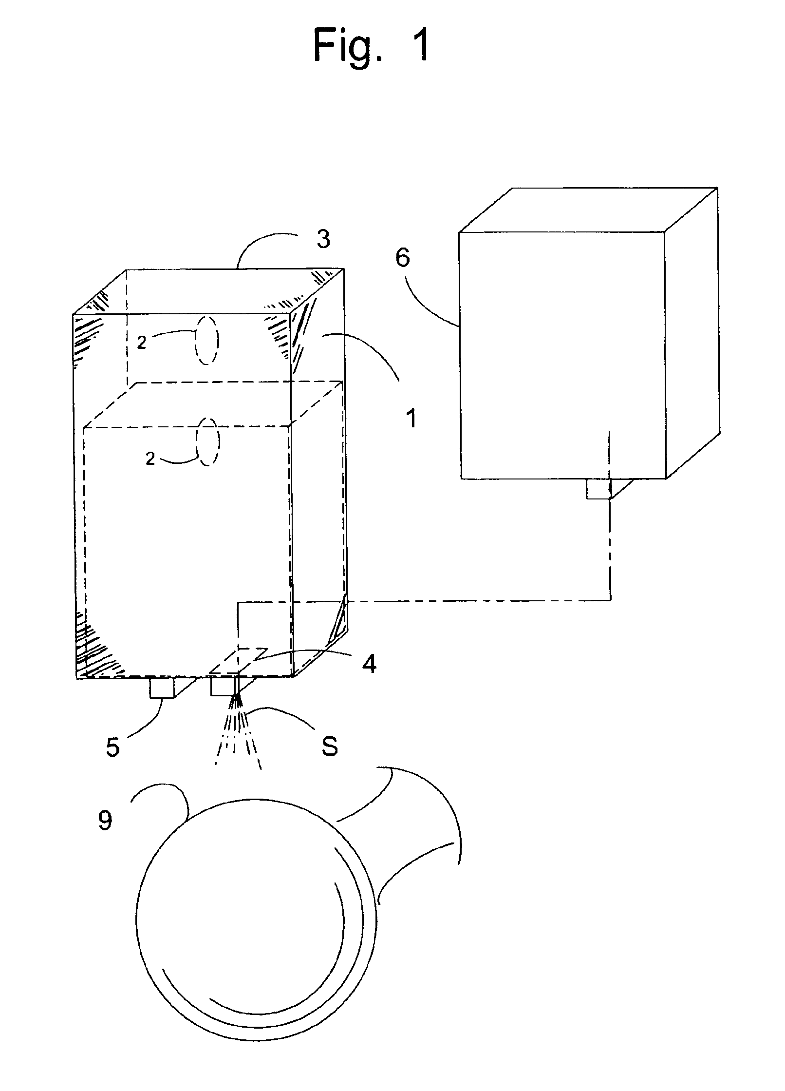
FIG. 1 schematically illustrates the components of a preferred embodiment of the device for disinfecting door knobs or handles. The device consists of a housing 3 that is adapted to contain a soap or disinfectant (hereinafter referred to as “disinfectant”) vessel 6 and a pump and battery compartment 1. The housing 3 may contain a hole or holes 2 to facilitate mounting the device on a door. In this case the holes should be of sufficient size to receive mounting screws. Other common ways of mounting the housing to the door may also be employed, e.g., double backed tape, straps, Velcro and glue. In some cases it may also be possible to hang the housing from the top of the door.

The disinfectant vessel 6 is designed to fit within the housing and to contain sprayable liquid disinfectant. The vessel may be permanently mounted in the housing as long as it contains provision for refilling when it is empty. In a preferred embodiment, however, the vessel will be removable and disposable, so th...


PUM


Abstract

A device for disinfecting door handles and knobs comprising a dispenser for soap or disinfectant adapted to spray the soap or disinfectant on the door handles or knobs when triggered by the motion of a hand.

Description

FIELD OF THE INVENTIONThis invention relates to sanitizing devices for disinfecting door handles and knobs, particularly to devices for spraying disinfecting agent on door handle surfaces.BACKGROUND OF THE INVENTIONIt is well known that bacteria and other microorganisms are the cause of many diseases and are easily transmitted from infected individuals to other persons if sanitary conditions are not maintained where such microorganisms thrive. Restrooms are places where bacteria, viruses and other disease-producing substances are found in great numbers. Indeed in public bathrooms the problem is particularly severe because these facilities are designed to dispose of large volumes of human waste, which contains up to 30% bacteria. It is not unusual to find disease causing organisms on a variety of surfaces in bathrooms, e.g., toilet seats, urinal and commode flush handles, faucet handles, door knobs, push plates, etc. Urine, feces, and other body wastes which contain disease organisms...

Claims


Application Information

Patent Timeline
IPC IPC(8): A01G27/00A61L2/22A61L2/18A47L25/00A47L25/04B05B17/00B05B9/03B05B9/04A62C13/62A62C13/66A62C13/00A62C35/58B67D5/08E03D9/02A61LA61L2/24B67D7/08E05B1/00
CPCA61L2/22E05B1/0069A61L2/24
Inventor CALLUENG, RONEL DOMINGO
Owner CALLUENG RONEL DOMINGO
Why Eureka
Try Eureka