Method and device for reeling up in the proper position a hot-rolled strip in a reeling installation

Inactive Publication Date: 2005-04-05
THYSSEN KRUPP STAHL AG +1
View PDF15 Cites 8 Cited by
  • Summary
  • Abstract
  • Description
  • Claims
  • Application Information

AI Technical Summary

Benefits of technology

It is particularly advantageous that the reference variable for the strip tension of the driving device is dimensioned such that the complete takeover of the draw-back by the driving device when the rolled strip is unthreaded from the last stand of the finishing train

Problems solved by technology

This also has the result that the side guide shoes are opened during the coiling operation.
The adjusting effect of this driving device with respect to the hot strip is based on a shift in the location of the point of action of the strip tensioning force and the resultant uneven elastic strip lengthening (bending) caused by pivoting of the upper driving roller.
Pivoting of the upper roller leads to opening of the driver gap on one side and consequently a shift in the point of action of the pressing force which the driving rollers exert on the strip.
This force-introducing situation brought about by the pivoting/tilting of the upper driving roller results in a moment exerted on the still centrally running strip that causes elastic transverse bending of the strip.
This results in a transverse shift of the strip in the driving device.
However, the quality requirements for the wound state are not completely satisfied with this method.
Since the armature current of the driving roller drives is controlled by the higher-level drive control, and can consequently also be limited, if a current limit that is too low is prescribed, the resultant tension in the strip between the mandrel and the driving device

Method used


Image

  • Method and device for reeling up in the proper position a hot-rolled strip in a reeling installation
  • Method and device for reeling up in the proper position a hot-rolled strip in a reeling installation
  • Method and device for reeling up in the proper position a hot-rolled strip in a reeling installation

Examples


Embodiment Construction

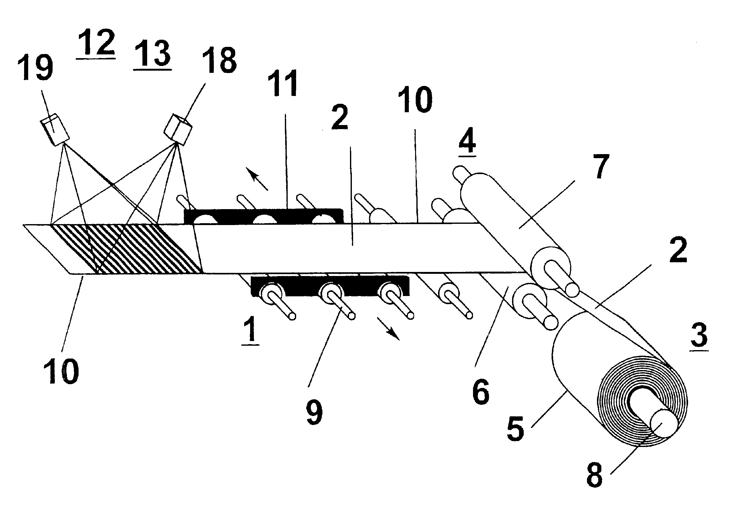
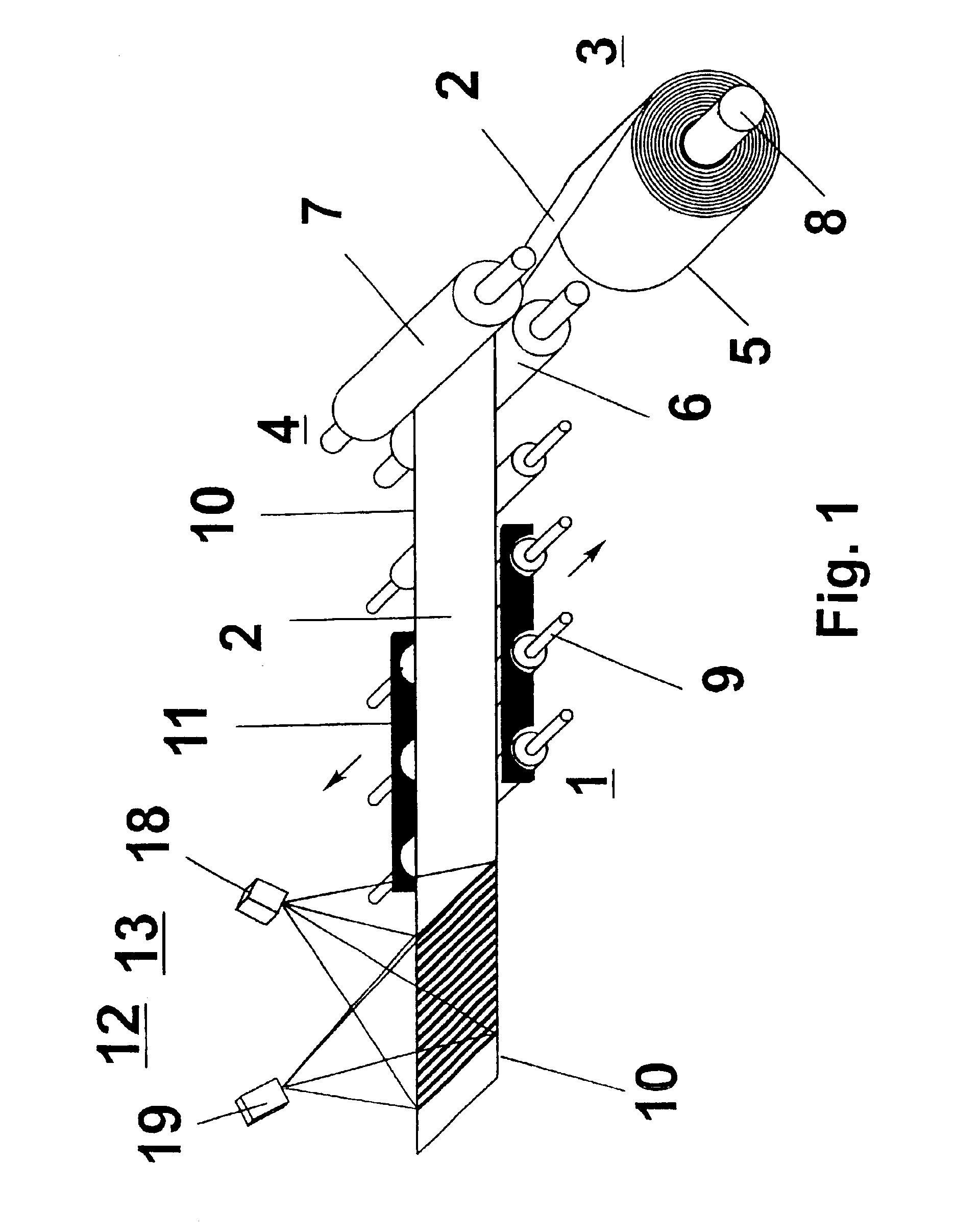
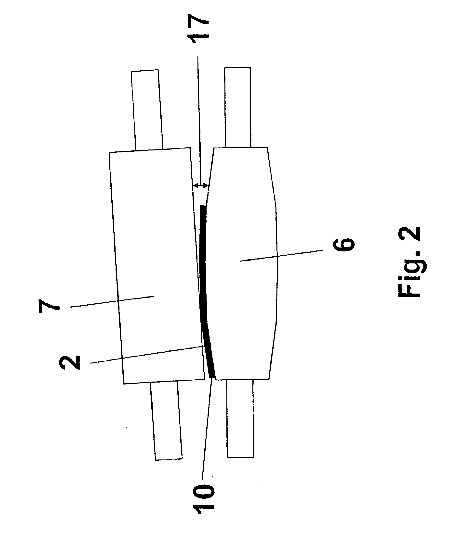
FIG. 1 shows a schematic side view of an end portion of a delivery table 1, which is connected on the input side to a finishing stand (not represented) of a hot strip train. On the delivery table 1, a finish-rolled hot strip 2 is transported in the direction of a coiling device 3 with an upstream driving device 4. The hot strip 2 can be wound up by the coiling device into coils 5. The driving device 4 arranged at the end of the delivery table 1 substantially comprises a lower driving roller 6 and an upper driving roller 7. The upper driving roller 7 can be adjusted in the direction of the lower driving roller 6 and laterally tilted by hydraulic piston / cylinder units (not represented) for setting and adjusting the gap between the driving rollers 6 and 7. In FIG. 2, which is a view of a detail of the driving rollers 6 and 7 of the driving device 4, a tilted upper driving roller 7 and a wedge-shaped driving roller gap 17 are represented. The alignment of the incoming rolled strip 2 in ...


PUM

PropertyMeasurementUnit
Speedaaaaaaaaaa
Surfaceaaaaaaaaaa
Tensionaaaaaaaaaa

Abstract

The invention relates to a method and a device for the positionally correct winding up of a metal strip in a coiling device, the hot strip being fed to the coiling device by a driving device with driving rollers, the driving rollers being tiltable in relation to one another by a controller by means of actuators for changing the gap between the driving rollers, and the controller being fed the position of the edge of the hot strip upstream of the driving device as a measured variable and as a setpoint reference variable, an optimization of the winding result of the rolled strip coil being achieved by the surface geometry of the rolled strip being determined as a measured variable and fed to the controller.

Description

FIELD OF INVENTION AND CROSS REFERENCE TO RELATED APPLICATIONSThe invention relates to a method for the positionally correct winding up of a metal strip, in particular a rolled hot strip, in a coiling device, the hot strip being fed to the coiling device by a driving device with driving rollers, the driving rollers being tiltable in relation to one another by a controller by means of actuators for changing the gap between the driving rollers and the resultant influencing of the lateral position of the hot strip, and the controller being fed the position of the edge of the hot strip upstream of the driving device as a measured variable and as a setpoint reference variable, and claiming the priority of German Patent Application 100 14 813.1-32, to the content of which reference is made.Furthermore, the invention relates to a device for the positionally correct winding up of a rolled hot strip in a coiling device, with a driving device with driving rollers feeding the hot strip to the ...

Claims


Application Information

Patent Timeline
IPC IPC(8): B21B37/68B21B39/00B21C47/34B21B38/02B21B39/14B21B38/00B21B15/00B21C47/00B21C47/02B21C47/26B21C51/00
CPCB21B37/68B21B39/006B21C47/3425B21C47/34B21B38/02B21B2015/0057B21B2265/08B21B39/14B21B39/00
Inventor MULLER, ULRICHWOLFF, ANDREASTHIEMANN, GERDDEGNER, MICHAEL
Owner THYSSEN KRUPP STAHL AG
Why Eureka
Try Eureka