
Method and apparatus for automatic assigning of devices

a technology of automatic assigning and devices, applied in the direction of measuring devices, instruments, using reradiation, etc., can solve the problems of difficult manual assigning, easy errors, and inability to properly perform the assignment process, so as to improve the success rate of the topological graph assignment, reduce the complexity of computation, and increase the accuracy of the device-assigning process

Inactive Publication Date: 2011-08-04
KONINKLIJKE PHILIPS ELECTRONICS NV
View PDF7 Cites 2 Cited by
  • Summary
  • Abstract
  • Description
  • Claims
  • Application Information

AI Technical Summary

Benefits of technology

[0004]To eliminate the drawbacks of the aforementioned prior art, increasing the accuracy of the device-assigning process, reducing the computation complexity of the assigning and improving the assigning success rate of the whole topological graph are several technical problems in the art that need to be solved. The so-called device comprises the aforesaid illumination devices, and also comprises temperature adjusting devices, audio regeneration devices and so on.
[0009]According to a method or an apparatus associated with one aspect of the present invention, by comparing the measured distance-related information, obtained through actual measurement, with the assumed distance-related information, under the assumption that the device corresponds to assigning nodes, the target devices having the smallest difference between assumed and measured information are selected as corresponding to the assigning nodes, and the assigning has a strong fault tolerance capacity and the assigning accuracy of the devices is substantially improved; according to a method or an apparatus relating to another aspect of the present invention, by determining multiple target devices corresponding to multiple nodes, along with a large safety margin based on multiple reference devices, the computation complexity of the assigning is reduced and the assigning accuracy of the devices is improved; according to a method or an apparatus relating to another aspect, by dividing the topological graph into sub-topology blocks, and assigning and verifying each sub-topology block respectively, the assigning success rate of sub-topology blocks is increased and error dispersion caused by device assigning errors in sub-topology blocks is avoided, so that the assigning success rate of the topological graph is increased.

Problems solved by technology

If the position of each device obtained by the system is not its real physical position, then this will cause the illumination array not to work properly.
Due to the large number of devices in a device array, it is very difficult to carry out manual assigning, and errors may easily occur if doing so.
However, several problems are encountered in the prior art.
The first problem is the assigning accuracy of the devices.
Since the transmission of radio signals is influenced by many factors, transmission parameters between two devices at the same distance may cause large deviations in different multi-path environments, in the case of different gains of antennas or different interferences, which may cause the distance determined by the transmission parameters to contain large errors, so that the assigning accuracy is affected.
The second problem is that, for spaces having two or more dimensions, the determination of positions of all the devices in the whole topological graph based on information about the distance between every two devices proves to be a difficult nondeterministic polynomial
The computation complexity will grow exponentially with the number of devices in the area.
The third problem is that, when the number of devices of a device array is very large, the error probability of the assigning in the whole topological graph will increase, and the erroneous assigning will then cause error dispersion, which will lead to more assigning errors.

Method used


Image

  • Method and apparatus for automatic assigning of devices
  • Method and apparatus for automatic assigning of devices
  • Method and apparatus for automatic assigning of devices

Examples


first embodiment

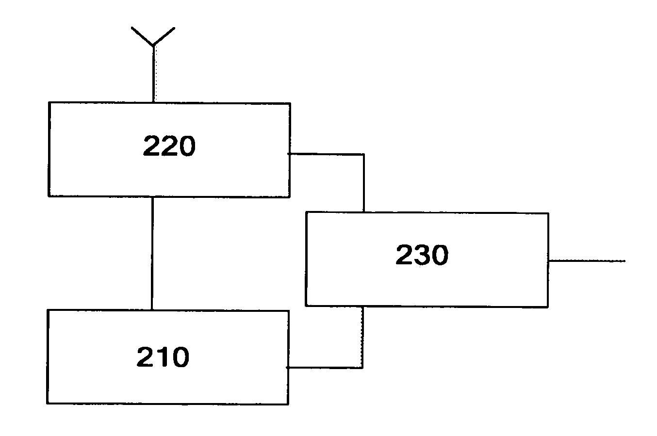
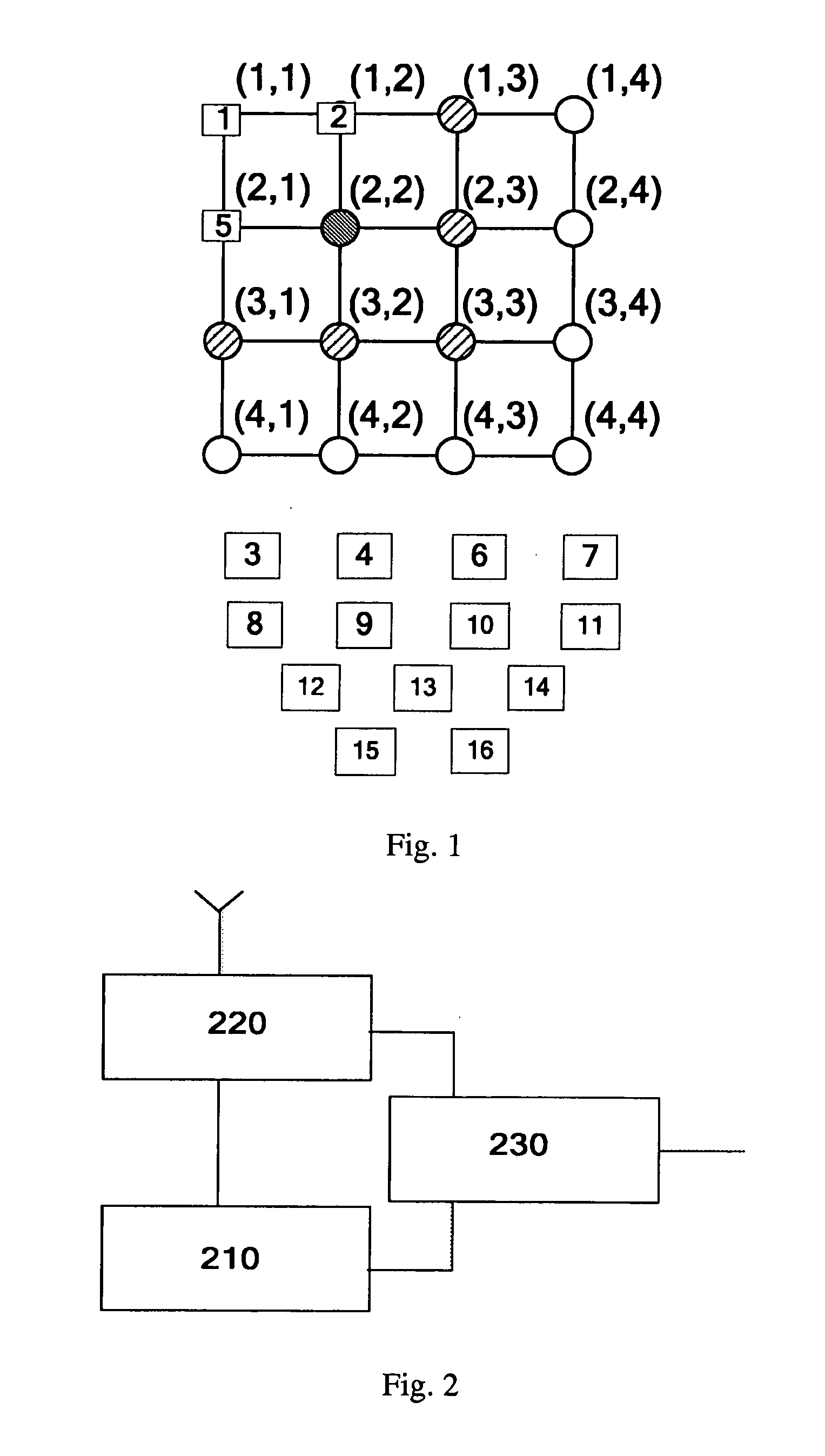
[0025]FIG. 1 schematically illustrates an illumination area based on a wireless network, wherein the topological graph of this illumination area is shown, i.e. the positions (1,1), (1,2), . . . (4,4) of each illumination node in the area are all known. There are illumination devices 1, 2, . . . , 16 installed at the nodes in the illumination area, but which illumination device corresponds to which node is unknown. As shown in FIG. 2, each node comprises an illuminating element 210, a wireless communication module 220, such as a ZigBee RF module, and a power supply 230. The wireless communication module 220 can perform wireless communication with wireless communication modules of other nodes, based on the ZigBee RF protocol or other protocols, and establish a wireless network 100. A signal sent by any one of the devices carries the unique identification information of the sending device; the receiving device can determine the sending device of the radio signals, based on the identifi...

second embodiment

[0048]Before the embodiment according to another aspect of the present invention is described, related knowledge about the safety margin of the assigning will be introduced first. As shown in FIG. 6, in the topological graph where nodes are distributed in a square grid shape, the reference devices 1 and 2 are placed at the reference node (1,1) and (1,2) respectively; other unknown target illuminating devices are placed at other nodes, and the configurations of the wireless communication modules of each illumination device are identical (for example, antenna gains and transmitting power are identical). When the assigning node (2,1) closest to the node (1,1) is assigned, since the distance between the node (2,1) and the node (1,1) is the smallest one of the distances between the node (1,1) and each of all nodes (except for the reference node (1,2)), the assigning can be based on the following principle: among all target devices, the illumination device having the largest RSSI between ...

third embodiment

[0073]The assigning success rate of the whole topological graph is related to the node number of the topological graph. As shown in FIG. 10, the simulation result illustrates the relation between the number of successful assigning operations and the node number of the topological graph; its vertical coordinate represents how many out of fiftyassigning operations are successful, the horizontal coordinate represents the standard deviation of measurement errors of RSSI (assume that the measurement error of RSSI is zero mean Gaussian distributed). The assigning method employed by the simulation is the method used in the aforesaid first embodiment. As can be seen, with the increase of nodes from sixteen to twenty-five (each comprises three reference nodes), the number of successful assigning operations is decreased. The reason is that the more nodes there are, the more likely wrong assigning will occur for the plurality of nodes on the whole. Meanwhile, wrongly assigned nodes may be take...


PUM


Abstract

In order to solve problems of low accuracy, high computation complexity and low assigning success rate of a topological graph existing on a large scale for device assigning, the present invention proposes methods and apparatuses for automatic assigning of devices. According to an aspect of the present invention, by comparing measured distance-related information between each target device and reference devices, and assumed distance-related information between reference devices and target devices corresponding to assigning nodes, and then selecting the target device with smallest difference to correspond to the assigning nodes, the assigning accuracy of devices is largely improved; according to another aspect of the present invention, based on multiple reference devices, by determining multiple target devices at multiple assigning nodes simultaneously with a large safety margin, assigning complexity is decreased; according to yet another aspect of the present invention, by dividing a large topological graph into blocks and assigning and verifying sub-topology blocks, the assigning accuracy of sub-topology blocks is improved, and error dispersion is avoided, so that the whole assigning success rate of the topological graph is increased.

Description

TECHNICAL FIELD[0001]The present invention relates to the automatic assigning of devices, particularly to a method and an apparatus for automatic assigning of devices, based on the wireless technology.BACKGROUND OF THE INVENTION[0002]Nowadays, device arrays are deployed on a large scale in various buildings and areas, such as arrays constituted by a very large number of illuminating devices, so as to provide multiple functions such as illumination, decoration or display functions. Systems such as a building management system remote monitor and manage the illumination device array, control each illumination device's turn-on, turn-off and switch its illuminating mode, and so on. In order to improve on multiple functions, like illumination, decoration or display, the system must be able to obtain the location of each illumination device accurately, for example, the corresponding relation between the Unique Identification (abbrev. UID) of each device and its installation node position o...

Claims


Application Information

Patent Timeline
Patent Type & Authority Applications(United States)
IPC IPC(8): H04W24/00
CPCG01S11/06G01S5/02G01S5/14Y02E10/52Y02E10/542H05B47/10G01S5/0252G01S5/021
Inventor CHEN, ZHIGANGFENG, LEIYANG, DAIQIN
Owner KONINKLIJKE PHILIPS ELECTRONICS NV
Learn More