
Expandable rigid knee airbag system

a knee airbag and expandable technology, applied in the direction of vehicular safety arrangements, pedestrian/occupant safety arrangements, vehicle components, etc., can solve the problems of passenger injury, airbags are generally large and thick, and problems have been noted to occur

Inactive Publication Date: 2005-04-05
AUTOLIV ASP INC
View PDF10 Cites 59 Cited by
  • Summary
  • Abstract
  • Description
  • Claims
  • Application Information

AI Technical Summary

Benefits of technology

The apparatus of the present invention has been developed in response to the present state of the art, and in particular, in response to the problems and needs in the art that have not yet been fully solved by currently available knee bolster airbag systems. Thus, it is an overall objective of the present invention to provide an inflatable rigid knee airbag system to assist in protecting and properly positioning a vehicle occupant during a collision event. To achieve these objectives, in accordance with the invention as embodied and broadly described herein, an inflatable rigid knee airbag system is provided.
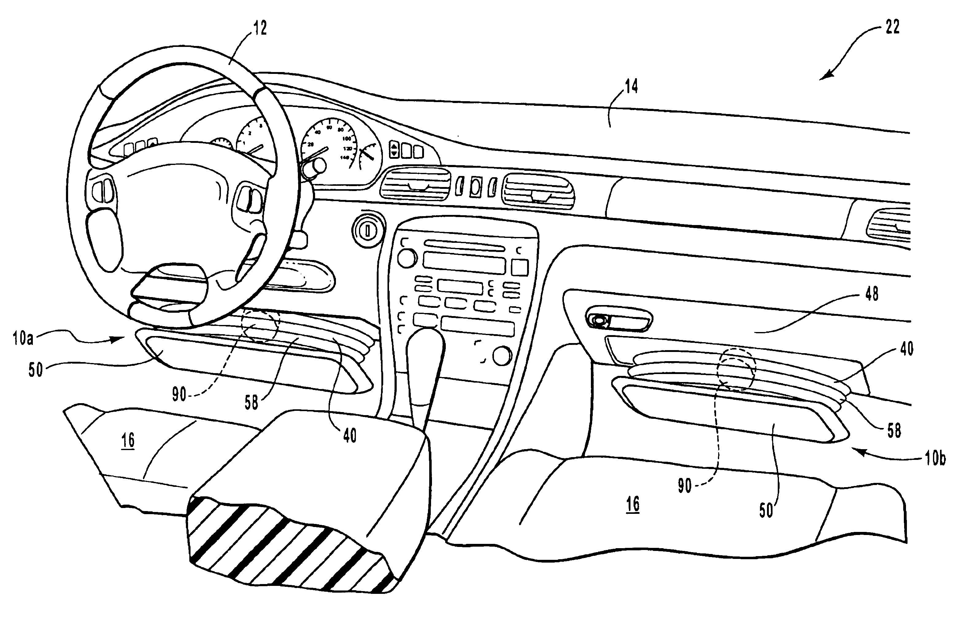
The front panel of the inflatable rigid knee airbag system of the invention is adapted for easy and aesthetic integration into a vehicle. Specifically, the front panel of the knee airbag may include a decorative cover panel for use as a knee bolster. This decorative cover panel may be a glove box door for use in protecting a vehicle occupant in the front passenger seat. Additionally, the decorative cover panel may be a contoured panel suitable for placement under the steering column or dashboard of a vehicle. This allows the airbag to be easily integrated into vehicle designs, and gives vehicle manufacturers a valuable option for increasing occupant safety.
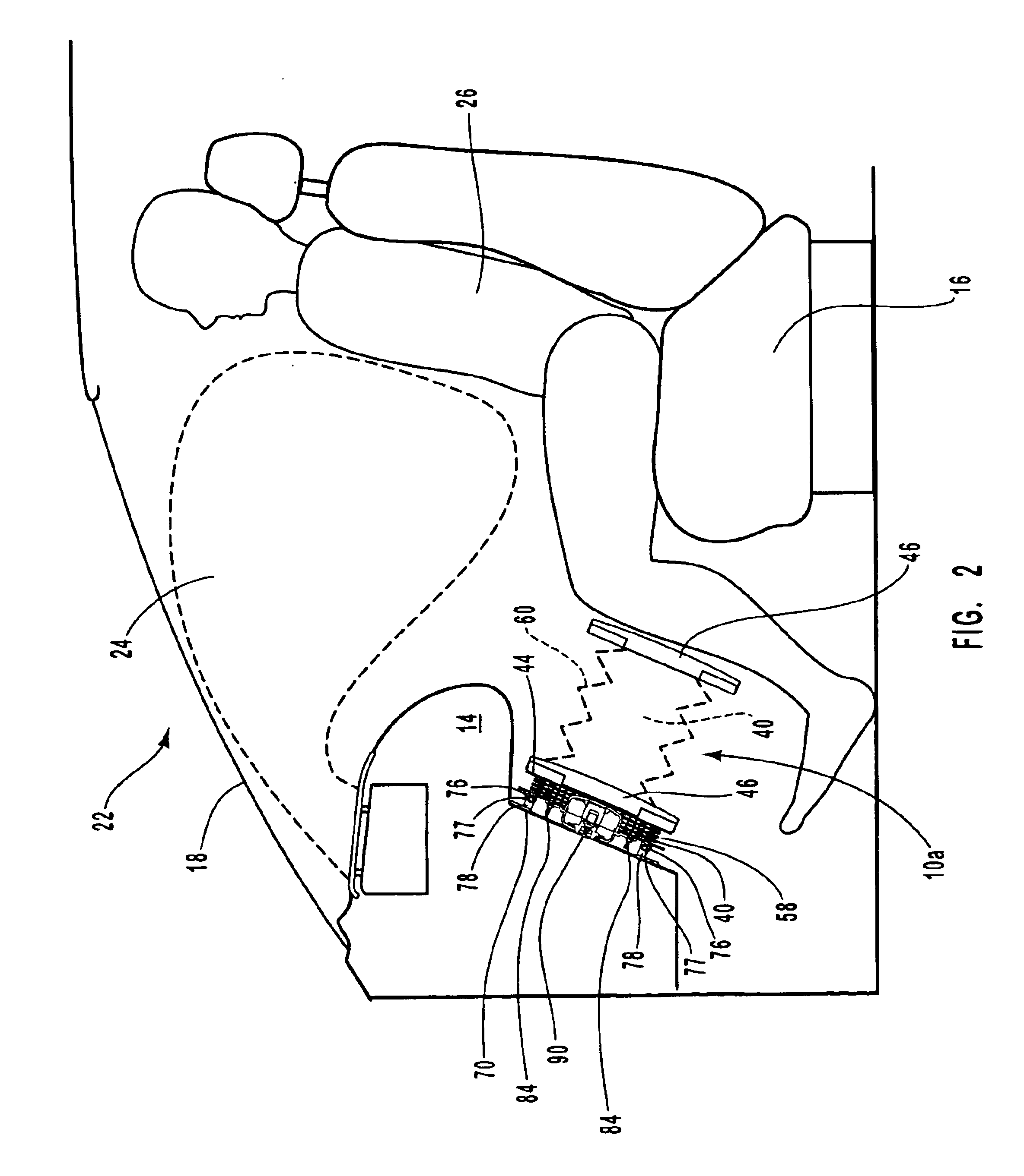
The bellows panel of the expandable rigid knee airbag system of the invention includes accordion folds to allow expansion of the airbag in front of a vehicle occupant's knees. Positioning the airbag thus helps to properly position the occupant during the impact and also to provide deceleration to the occupant by deforming when the occupant strikes the rigid airbag. The bellows panel may comprise at least one accordion fold to allow airbag expansion upon activation of the inflator. Alternatively, the bellows panel may include at least four accordion folds to allow proper airbag expansion.

Problems solved by technology

These airbags are generally large and thick.
If the airbag cover were allowed to detach and freely move into the passenger compartment, it could cause injury to a passenger.
Problems have been noted to occur when the occupant is “out of position” in regard to this presumed placement when a collision event occurs and the airbag deploys.
Similarly, problems may occur when the occupant, though possibly at first in the predicted position, strikes a glancing blow to the airbag, and is then deflected out of the airbag before proper deceleration can occur.
Out of position injuries may be attributed in part to the fact that most airbag systems have been primarily designed for deployment in front of the torso of an occupant.
During a front-end collision, there is a tendency for an occupant, particularly one who is not properly restrained by a seat belt, to slide forward along the seat.
This results in poor kinematics and positioning when the occupant interacts with a frontal airbag such as a driver's side or passenger's side airbag.
Such knee bolster airbag systems, like many other airbag systems, suffer from high cost and engineering problems.
Specifically, knee bolster airbags are difficult to design to be mounted in the tight spaces available under the steering column or dashboard in order to be properly positioned to contact a vehicle occupant's knees.
Such systems require the use of costly gas guides suitable for conducting hot inflation gases from the inflator to the airbag.
These elements add bulk to the inflator, thus increasing its space requirements, and also add expense to the cost of the inflator.
Finally, in some specific applications, such as mounting an airbag in the door of a glove box of a vehicle, fabric airbags have proven very difficult to install.

Method used


Image

  • Expandable rigid knee airbag system
  • Expandable rigid knee airbag system
  • Expandable rigid knee airbag system

Examples


Embodiment Construction

The presently preferred embodiments of the present invention will be best understood by reference to the drawings, wherein like parts are designated by like numerals throughout. It will be readily understood that the components of the present invention, as generally described and illustrated in the figures herein, could be arranged and designed in a wide variety of different configurations. Thus, the following more detailed description of the apparatus, system, and method of the present invention, as represented in FIGS. 1 through 6, is not intended to limit the scope of the invention, as claimed, but is merely representative of presently preferred embodiments of the invention.

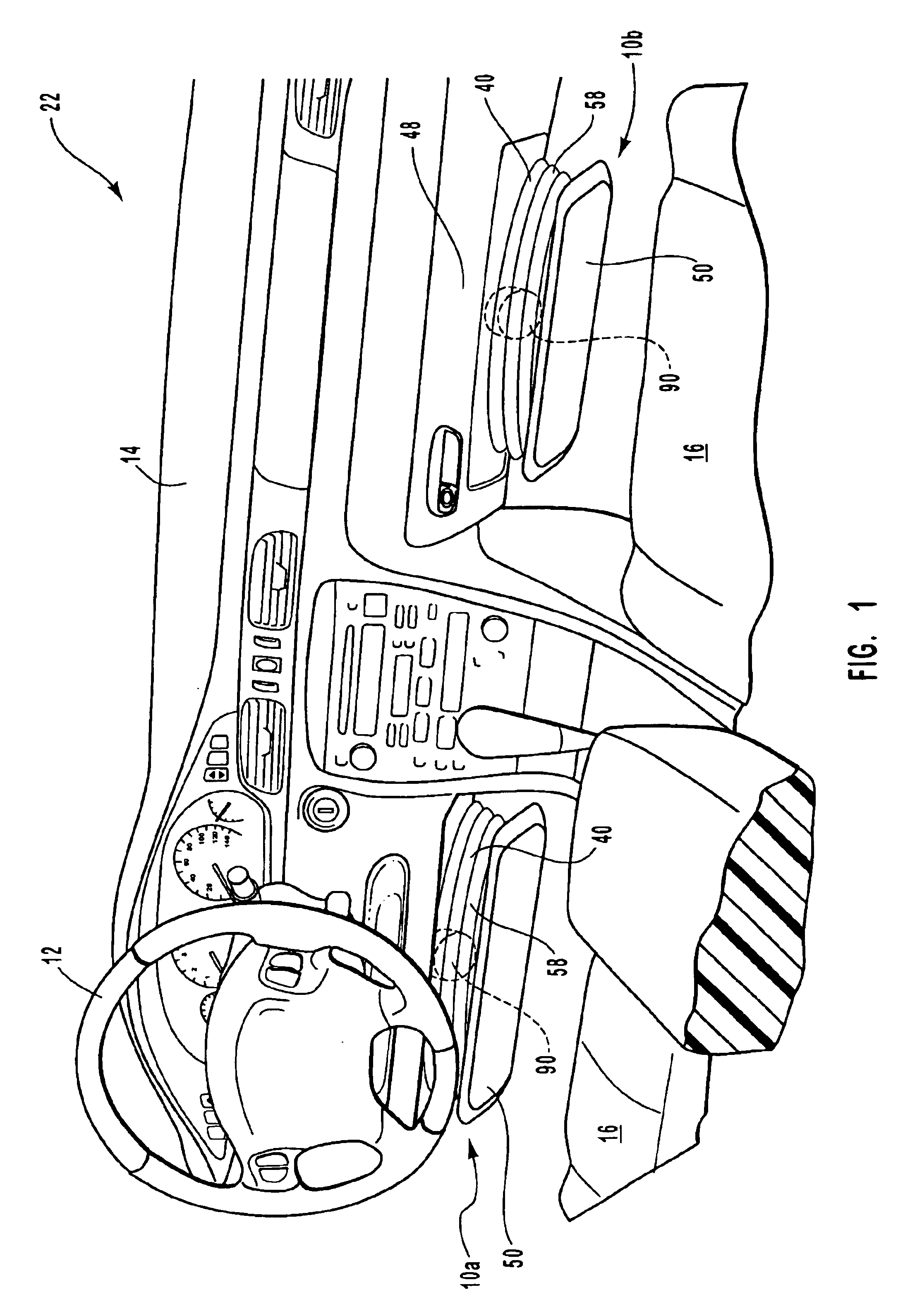
Referring now to FIG. 1, expandable rigid knee airbag systems 10a and 10b of the invention are shown mounted and inflated in a vehicle 22. A first expandable rigid knee airbag system 10a is shown placed under the steering wheel 12 of the vehicle 22 and inflated. A second expandable rigid knee airbag system 10b...


PUM


Abstract

An inflatable rigid knee airbag system for assisting in positioning and decelerating a vehicle occupant is disclosed. The system includes an inflatable knee airbag having a front panel, an annular, accordion-folded bellows panel, and a rear panel having an inflation orifice and mounting brackets; and a pyrotechnic inflator. The system helps to improve the kinematics of a vehicle occupant in relation to a primary airbag cushion by bolstering the knees of the occupant. The system of the invention may be mounted in a vehicle in a panel under the steering column, in the door of a glove box, or in the lower section of the instrument panel of the vehicle directly in front of the occupant's lower legs.

Description

BACKGROUND OF THE INVENTION1. Field of the InventionThe present invention relates to inflatable airbags for protecting vehicle occupants during collision events. More specifically, the present invention relates to an expandable rigid knee airbag system that facilitates proper occupant positioning in order to reduce lower leg and other injuries in vehicle collisions.2. Description of Related ArtInflatable airbags enjoy widespread acceptance as passive passenger restraints for use in motor vehicles. This acceptance has come as airbags have built a reputation of preventing numerous deaths and injuries over years of development, testing, and use. Studies show that in some instances, the use of frontally placed vehicular airbags can reduce the number of fatalities in head-on collisions by 25% among drivers using seat belts and by more than 30% among unbelted drivers. Other statistics suggest that in a frontal collision, the combination of a seat belt and an airbag can reduce the incidenc...

Claims


Application Information

Patent Timeline
Patent Type & Authority Patents(United States)
IPC IPC(8): B60R21/16B60R21/20B60R21/04B60R21/00B60R21/045B60R21/215B60R21/217B60R21/231B60R21/235
CPCB60R21/206B60R21/217B60R21/231B60R21/235B60R21/045B60R2021/23528B60R2021/21525B60R2021/23169B60R2021/23519B60R2021/23523B60R2021/0051
Inventor ENDERS, MARK L.HAYS, ROBERT J.
Owner AUTOLIV ASP INC
Learn More