Light cutter of a lamp for projector

a projector and light cutter technology, applied in the field of projectors, can solve the problems of reducing the life of the fan, reducing the cooling efficiency, and unable to efficiently exhaust airflow, so as to effectively shelter the radiation heat produced, reduce the temperature of the projector casing, and improve the quality of the image

Inactive Publication Date: 2005-04-05
CORETRONIC
View PDF4 Cites 3 Cited by
  • Summary
  • Abstract
  • Description
  • Claims
  • Application Information

AI Technical Summary

Benefits of technology

An object of the present invention is to provide a light cutter of a lamp for projector, which directly shelters the illuminating light toward a ventilator and prevents the light leaking to raise the quality of the images.
Another object of the present invention is to provide a light cutter of a lamp for projector, which can effectively shelter the radiation heat produced by the light lamp to lower the temperature of the projector casing.
Another object of the present invention is to provide a light cutter of a lamp for projector, which can reduce the wind resistance of the ventilator to raise the airflows and increase the cooling efficiency.
Another object of the present invention is to provide a light cutter of a lamp for projector, which can reduce the radiation heat loading of the projector, lower the working temperature and rotational speed of each component, rise the lifetime of the components, and lower the noises of the projector.
To achieve the above and other objects, the present invention uses a fan to produc

Problems solved by technology

Therefore, rising the cooling efficiency and light sheltering of the projector to raise the market competition is a challenge of the business.
The airflow can't be exhausted smoothly, lowering the cooling efficiency.
Therefore, the projector of the prior art has no choice but to raise the rotati

Method used


Image

  • Light cutter of a lamp for projector
  • Light cutter of a lamp for projector
  • Light cutter of a lamp for projector

Examples


Embodiment Construction

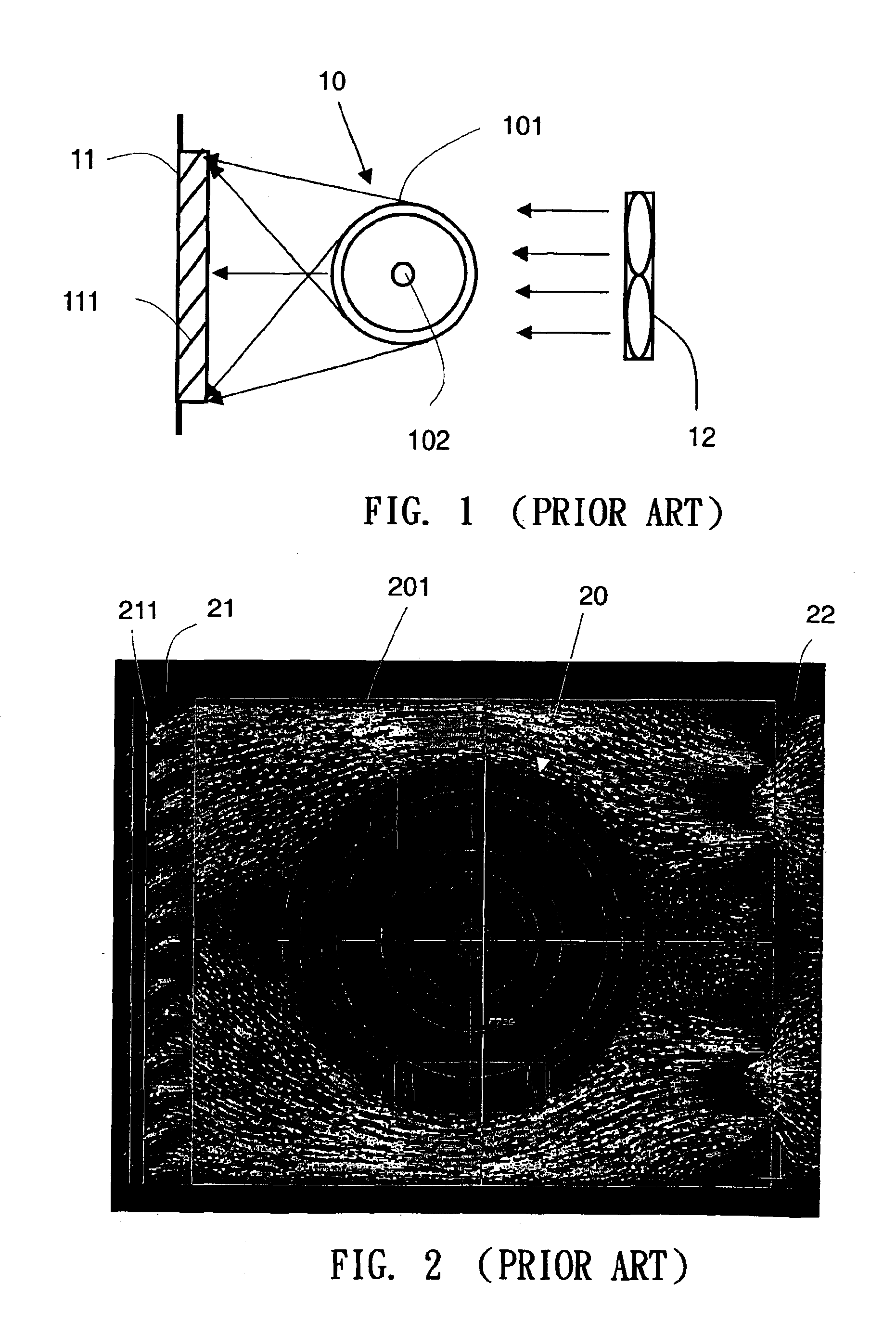
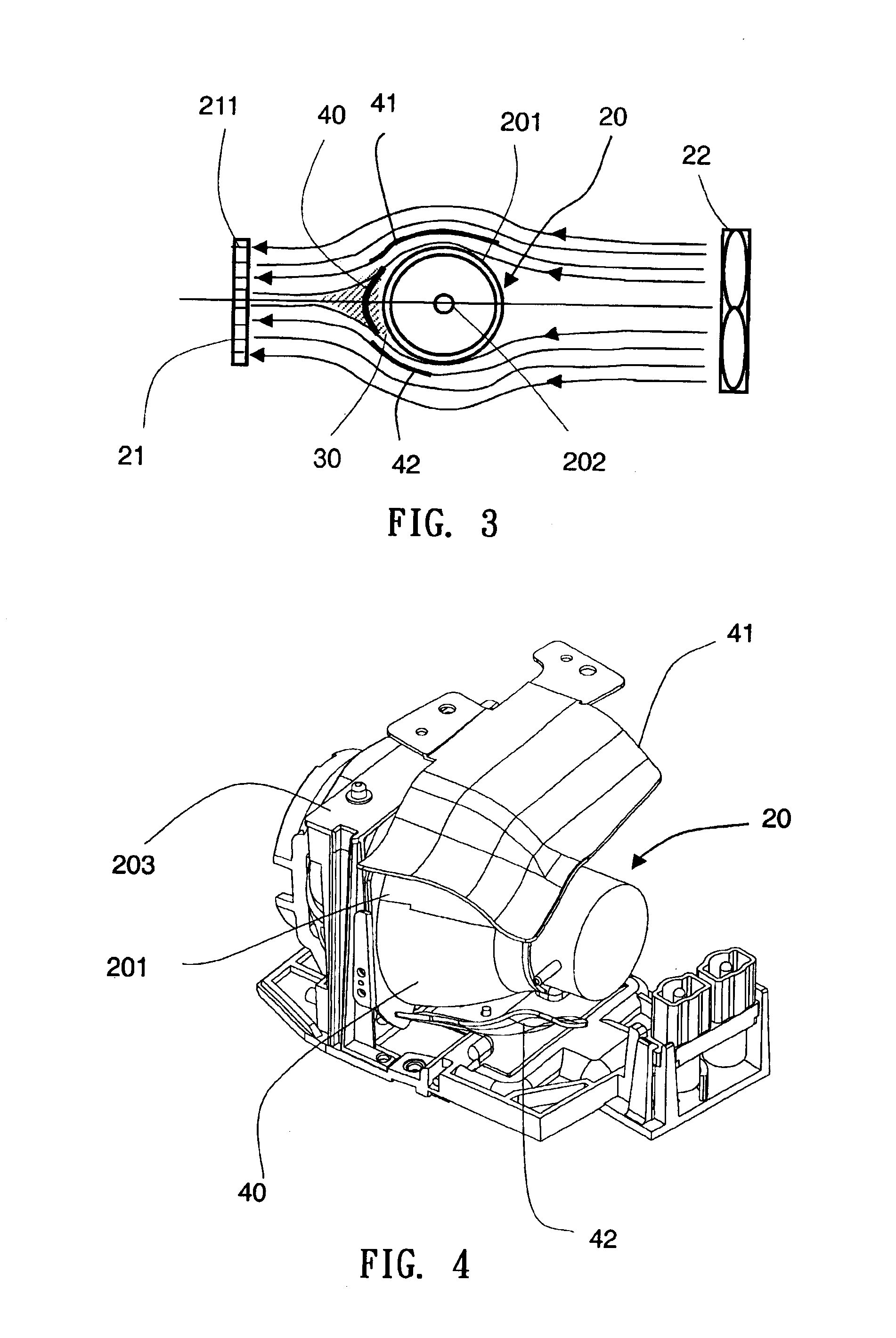
Referring to the FIG. 2 is a simulation experiment view showing the streamline of a light lamp of the prior art. Adjacent to the one side of a light lamp 20 is a ventilator 21, the ventilator 21 having a guide 211, and the other side of the light lamp 20 is a cooling fan 22. A lamp reflector 201 of the light lamp 20 is cylinder-like or core-like. As the rotational speed rising to a certain loading, the air speeds distribution of the guide 211 outlets beside the light lamp 20, the upper and lower sides without shielding by the light lamp 201, maintain the highest speed 4.55 m / s. But closing to the central of the side surface of the light lamp 20, the air speeds gradually decrease to 0 m / s. According to the streamline of the air speeds distribution, it is apparent that the downstream of the light lamp 20 forms a wake region.

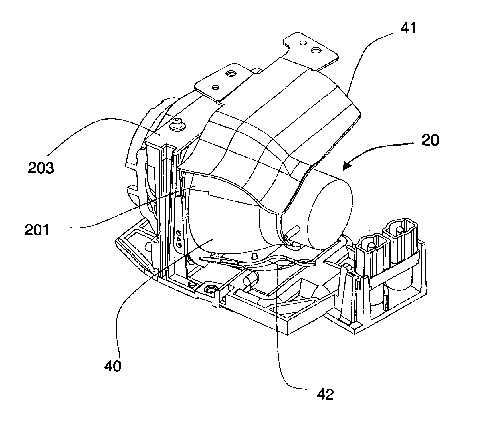
Referring to FIG. 3, FIG. 4 and FIG. 5, the cylinder-like or core-like lamp reflector 201 of the light lamp 20, by the streamline distribution according to the hyd...


PUM


Abstract

A light cutter device. The device uses a fan to produce airflows flowing through a cylinder-like or core-like lamp reflector so as to form a wake region downstream of the lamp reflector. A front light cutter is placed on the wake region, and an upper light cutter and a lower light cutter are respectively installed at both sides of the lamp reflector. One end of the light cutters is mounted at a lamp housing by bolts, and the other end maintains a distance from the lamp reflector and extends to the back end of the lamp along the contour of the lamp reflector. The light cutters are able to shelter the bright light beam, emitting from the lamp, towards the outlet of airflows to not leak out of the projector and lead airflows to cool the lamp reflector. As a result, there is no need to install a decline guide on the airflows for sheltering the light so that the block o the airflow outlet decreases.

Description

BACKGROUND OF THE INVENTION1. Field of the InventionThe present invention relates to a projector, and more particularly to a light cutter of a lamp for projector.2. Description of the Related ArtAs the development of the technology, the projectors are used in various fields. With using the high power lamps and the images brightness rising, the cooling and light leaking of the projector is more important. Therefore, rising the cooling efficiency and light sheltering of the projector to raise the market competition is a challenge of the business.Referring to FIG. 1 is a light lamp 10 of a projector and a ventilator guides 111 of the prior art. A generally light lamp 10 of the projector, which is formed with a glass lamp reflector 101 surrounded a filament 102. For the filament 102 can emit a high brightness light, which uses the high power light lamp 10 and electroplates or daub a high reflection surface within the inner surface of the glass lamp reflector 101 to reflect illuminating ...

Claims


Application Information

Patent Timeline
IPC IPC(8): F21V29/02F21V29/00F21V15/00F21V15/06F21V29/15
CPCF21V29/15F21V29/02F21V29/67
Inventor HSU, NIEN-HUIHSU, SEN-MING
Owner CORETRONIC
Why Eureka
Try Eureka