Cable end connecotr assembly with improved contact

Inactive Publication Date: 2005-04-05
HON HAI PRECISION IND CO LTD
View PDF5 Cites 18 Cited by
  • Summary
  • Abstract
  • Description
  • Claims
  • Application Information

AI Technical Summary

Benefits of technology

An object, therefore, of the present invention is to provide a cable end connector assembly having

Problems solved by technology

Generally, for a conventional electrical cable end according to the SATA, in assembly process, in order to have good quality of soldering, alignment between conductors and contacts is very time consuming which leads to a high

Method used


Image

  • Cable end connecotr assembly with improved contact
  • Cable end connecotr assembly with improved contact
  • Cable end connecotr assembly with improved contact

Examples


Example

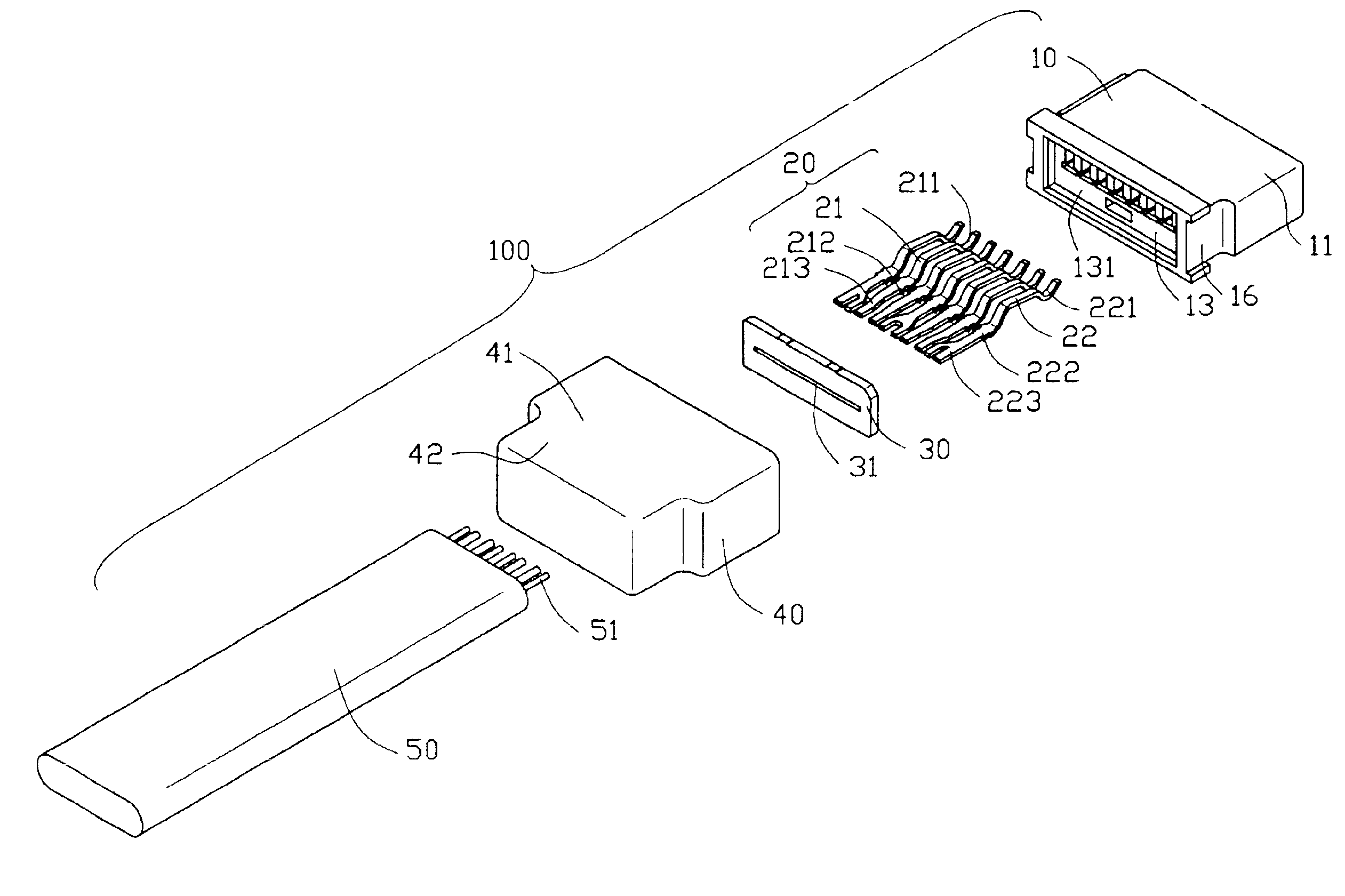
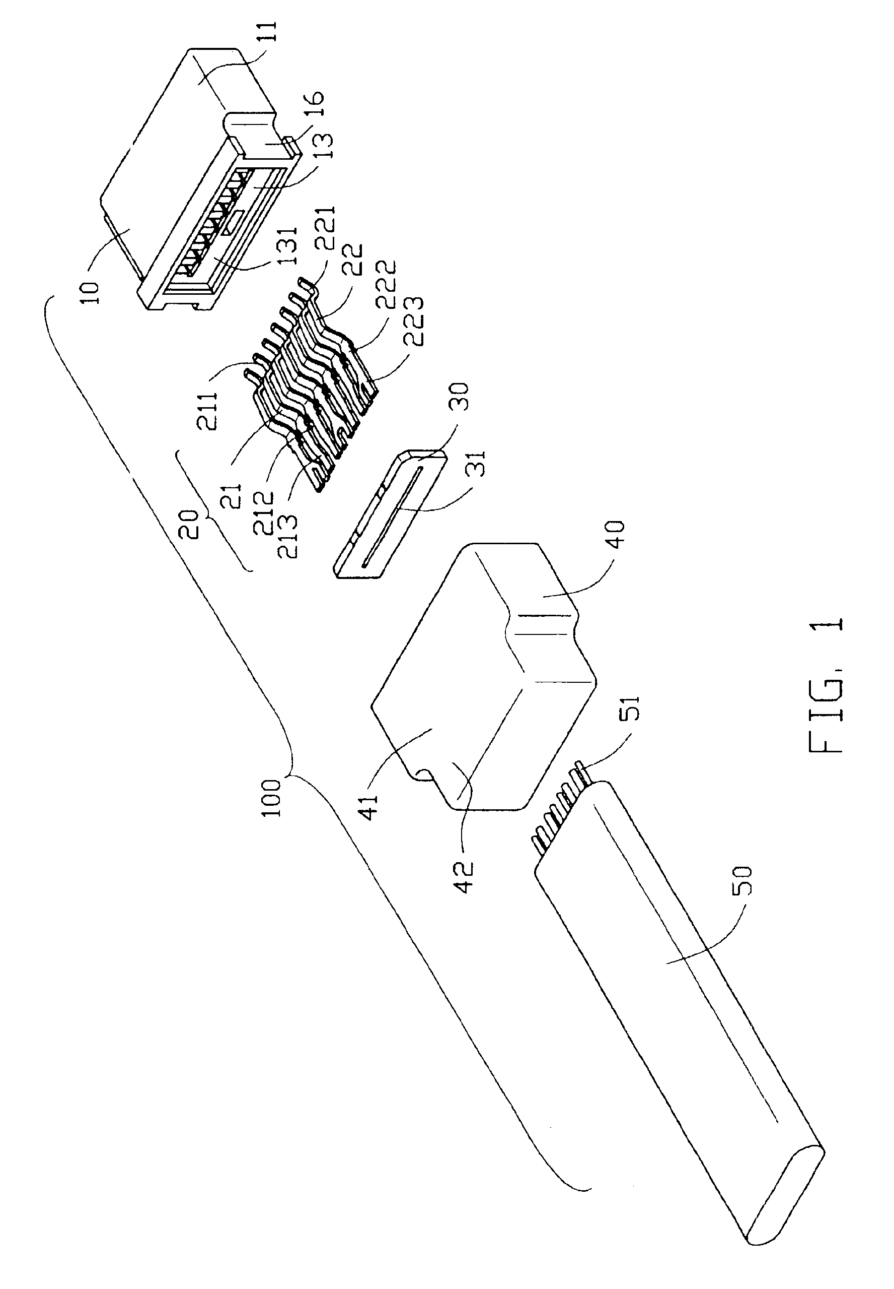
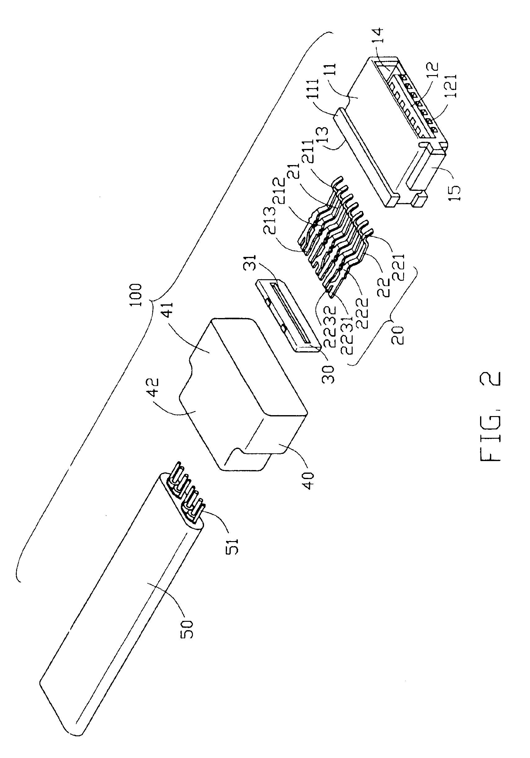
Referring to FIGS. 1-3, a cable end connector assembly 100 comprises an insulative housing 10, a contact insert 20, a spacer device 30, a cable 40, and an over-molding cover 50 separately drawn for ease of illustration and description.

Referring to FIGS. 1-2, the insulative housing 10 comprises a rectangular base 11. The base 11 has a mating section 12 and a rear portion 13. The base 11 defines a receiving space 14 for receiving the mating portion of a complementary connector (not shown). The mating section 12 defines a plurality of passageways 121 extending rearwardly through the base 11. The rear portion 13 defines a rectangular depression 131. A pair of flanges 111 are formed on an upper and a lower surfaces of the base 11. The base 11 defines a recess 16 on a lateral side thereof. The base 11 further forms a projection 15 at another lateral sides thereof for guiding the cable end connector 100 to mate with the complementary connector.

The contact insert 20 comprises a plurality of...


PUM


Abstract

A cable end connector assembly including an insulative housing (10), a plurality of signal and grounding contacts (21), (22), a spacer device (30), a cable (40), and an over-molding cover (50). The insulative housing has a base, the base having a mating section defining a receiving space therein adapted for receiving a mating portion of the complementary connector. The signal and grounding contacts are mounted in the housing, each contact has an engaging portion, a rear connecting portion, and a tail portion extends rearwardly from the connecting portion, at least one tail portion of the grounding contact has a fork-shape. The cable has a number of conductors each electrically connecting a corresponding contact. The cover is over-molded with and encloses a rear end of the housing and the front end of the cable.

Description

BACKGROUND OF THE INVENTION1. Field of the InventionThe present invention relates to an electrical connector assembly, particularity to a cable end connector including improved contact members for transmitting signal and grounding contacts, whereby the connector can achieve a good electrical connection with a complementary connector.2. Description of Related ArtSerial Advanced Technology Attachment (SATA) is a high speed interface between storage devices (such as hard disks, CD-ROMs, and DVDs) and a mother board. Because of the numerous advantages of Serial ATA, it is developed as a replacement for Parallel ATA and Ultra ATA.Generally, for a conventional electrical cable end according to the SATA, in assembly process, in order to have good quality of soldering, alignment between conductors and contacts is very time consuming which leads to a high manufacturing cost, and the cable alignment process needs long time for aligning the conductors of the cable connecting the signal and gro...

Claims


Application Information

Patent Timeline
IPC IPC(8): H01R13/658H01R13/58
CPCH01R13/65802H01R13/5845H01R13/6597
Inventor LEE, GEORGE
Owner HON HAI PRECISION IND CO LTD
Why Eureka
Try Eureka