Utility line pole having alignment indicator and associated methods

a technology of utility line and alignment indicator, which is applied in the direction of overhead line/cable apparatus, electrical cable installation, substation/switching arrangement casing, etc., can solve the problems of exacerbated problems, difficulty in locking individual sections of telescoping poles, and inability to easily position multiple pole sections

Active Publication Date: 2005-04-05
UTLITY SOLUTIONS
View PDF16 Cites 26 Cited by
  • Summary
  • Abstract
  • Description
  • Claims
  • Application Information

AI Technical Summary

Benefits of technology

The first and second pole segments are readied for use by extending the first pole segment from the retracted position within the second pole segment and connecting a collapsible lock member positioned adjacent the proximal first pole end of the first pole segment through a distal second pole end opening positioned in the distal second pole end. The collapsible lock member is positioned in alignment with the alignment indicator of the first outer pole segment surface. Correspondingly, the second pole segment is in alignment with the second alignment indicator of the second outer pole segment surface. The alignment with and connection of the collapsible lock member and the distal second pole end opening is efficiently accomplished by extending the first pole segment from the retracted position within the second pole segment while viewing the pair of alignment indicators to maintain alignment of the collapsible lock member with the opening in the distal second pole end of the second pole segment during such extension.
According to an embodiment of the present invention, a method of using the portable utility power line pole includes providing an assembled portable utility power line pole adapted to be held in the hand of a user. The portable utility power line pole includes a pole body having a distal pole body end and a power line tool connector connected thereon and adapted to mount a power line tool for use in association with electrical power distribution lines. An alignment indicator is positioned on an outer pole body surface of the pole body in alignment with the power line tool connector to provide the user visualization of a user selected orientation of the power line tool when mounted on the power line tool connector and when the user manipulates the portable utility power line pole at a proximal pole body end of the pole body to select the orientation of the power line tool. This can be best accomplished through use of an alignment indicator in the form of a visible line that extends substantially the lengthwise extent of at least the visible extents of the outer pole body surface.
Method also includes mounting the power line tool to the power line tool connector in alignment with the alignment indicator to provide the user visualization of the direction of the power line tool when manipulating the portable utility power line pole. The user manipulates the portable utility power line pole while viewing the alignment indicator at the proximal pole body end of the pole body to maintain continuous visualization of the direction of the utility power line tool at the distal pole body end of the pole body of the portable utility power line pole. This prevents the user from inadvertently and unwarrantedly contacting other electrical power distribution line equipment with the utility power line tool.
Advantageously, the portable utility power line pole alignment indicator provides the user visualization of the orientation of a power line tool positioned on the farthest most end of the pole when manipulating the pole at its nearest most end even when faced with bad weather or low-light conditions. Advantageously, the portable utility power line pole alignment indicator in the telescoping portable utility power line pole embodiment is easily viewable by the user to allow the user to visualize the location of means for connecting a pair of poles such as a collapsible lock member of the inner pole section and opening in the outer pole section, negating the requirement for the user to have to radially twist the two pole sections relative to each other to “feel” for the member in order to align the member with the hole of the adjacent outer pole section until engagement occurs. Advantageously, the user is provided visualization so as to easily position multiple pole sections in a retracted position where a single member engages each of the holes of corresponding adjacent outer pole sections.

Problems solved by technology

As a result of such a highly diverse and non-uniform manner in which the electrical power distribution lines are positioned and mounted, the access distances between the electrical power distribution lines and the maintenance personnel vary substantially.
The means for locking the individual sections of the telescoping pole can, however, be problematic.
This rotation typically results in a misalignment of the button of the inner pole section with the corresponding hole in the adjacent outer pole section which prevents engagement of the hole with the button.
This problem is exacerbated when trying to retract all of the pole sections such that a single button engages each of the holes of corresponding adjacent outer pole sections.
These markings, however, tend to be difficult for maintenance personnel to see, especially when faced with bad weather or low-light conditions.
These markings also have been shown to be even less effective when used to align the poles during retraction.
Often, maintenance personnel have faced difficulty in manipulating the tool due to the distance between the eyes of the user and the tool itself, the chief complaint being that it is difficult to visualize the direction (spatial orientation) of the tool at the end of the telescoping pole.
This has proved only marginally successful as the telescoping pole is often inadvertently rotated during the repositioning process.
When used to manipulate a tool, maintenance personnel face difficulty due to the distance between their eyes and the tool itself.
As with telescoping poles, the chief complaint is that it is difficult to visualize the direction or spatial orientation of the tool at the end of the pole.
When used to install a hot line clamp, maintenance personnel are faced with even greater difficulty because of the necessity for knowing the radial direction the hook or jaw will extend prior to releasing the clamp.
This too has also proved only marginally successful.

Method used


Image

  • Utility line pole having alignment indicator and associated methods
  • Utility line pole having alignment indicator and associated methods
  • Utility line pole having alignment indicator and associated methods

Examples


Embodiment Construction

Embodiments of the present invention will now be described more fully hereinafter with reference to the accompanying drawings, which illustrate embodiments of the invention. This invention may, however, be embodied in many other different forms and should not be construed as limited to the illustrated embodiments set forth herein. Rather, these embodiments are provided so that this disclosure will be thorough and complete, and will fully convey the scope of the invention to those skilled in the art. Like numbers refer to like elements throughout. Prime notation, if used, indicates similar elements in alternative embodiments.

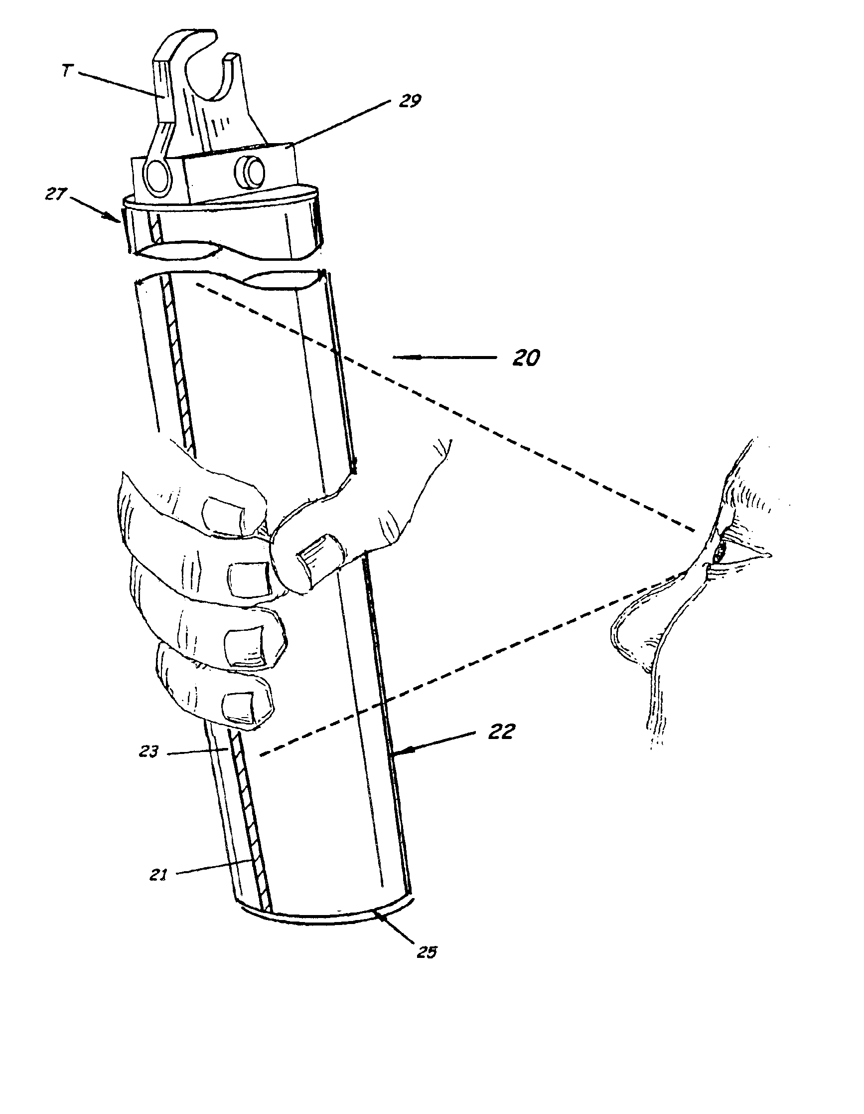
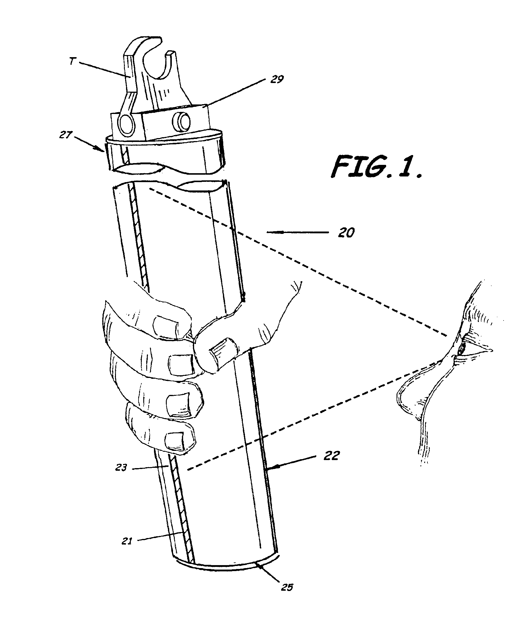
As illustrated in FIG. 1, embodiments of the present invention advantageously provide a portable utility power line pole 20 adapted to be held in the hand of a user for use in association with electrical power distribution lines and having an alignment indicator 21 to provide the user continuous visualization of a user selected orientation of a utility power line...


PUM


Abstract

A portable utility power line pole and associated methods of assembly and use are provided. The portable utility power line pole includes a pole body adapted to be held in the hand of a user. The portable utility power line pole also can include a tool connector adapted to mount a utility power line tool for use in association with electrical power distribution lines. An alignment indicator in the form of a visible line is positioned on an outer surface of the pole body in alignment with the tool connector to provide the user visualization of a user selected orientation of the utility power line tool when mounted on the tool connector and when the user manipulates the portable utility power line pole at a proximal end of the pole body to select the orientation of the utility power line tool.

Description

BACKGROUND OF THE INVENTION1. Field of the InventionThe present invention relates generally to portable extension poles. In more specific aspects, the present invention relates to portable poles used in the electrical distribution system field and methods associated therewith.2. Description of the Related ArtThe accessibility of electrical power distribution lines varies substantially because the lines are installed both above ground at various elevations and below ground in underground electric power distribution systems. As a result of such a highly diverse and non-uniform manner in which the electrical power distribution lines are positioned and mounted, the access distances between the electrical power distribution lines and the maintenance personnel vary substantially. For example, an above ground electrical power distribution line may be 10 feet or more from the maintenance person thus requiring a pole of at least 10 feet in length in order to reach the line. On the other hand...

Claims


Application Information

Patent Timeline
Patent Type & Authority Patents(United States)
IPC IPC(8): H02G3/04H02G1/02
CPCH02G1/02
Inventor WOOD, EUGENE H.NOLTE, MICHAEL G.FRANKLIN, DAVID A.
Owner UTLITY SOLUTIONS
Why Eureka
Try Eureka