Automatic transfer switch systems and controllers

a technology of automatic transfer switch and controller, which is applied in the field of electric switches, can solve the problems that the automatic transfer switch controller known is unable to communicate with external devices for softwar

Inactive Publication Date: 2005-04-05
GENERAL ELECTRIC CO
View PDF28 Cites 81 Cited by
  • Summary
  • Abstract
  • Description
  • Claims
  • Application Information

AI Technical Summary

Problems solved by technology

Further, known automatic transfer switch controllers are unable to communicate with external devices for software selection of options.

Method used


Image

  • Automatic transfer switch systems and controllers
  • Automatic transfer switch systems and controllers
  • Automatic transfer switch systems and controllers

Examples


Embodiment Construction

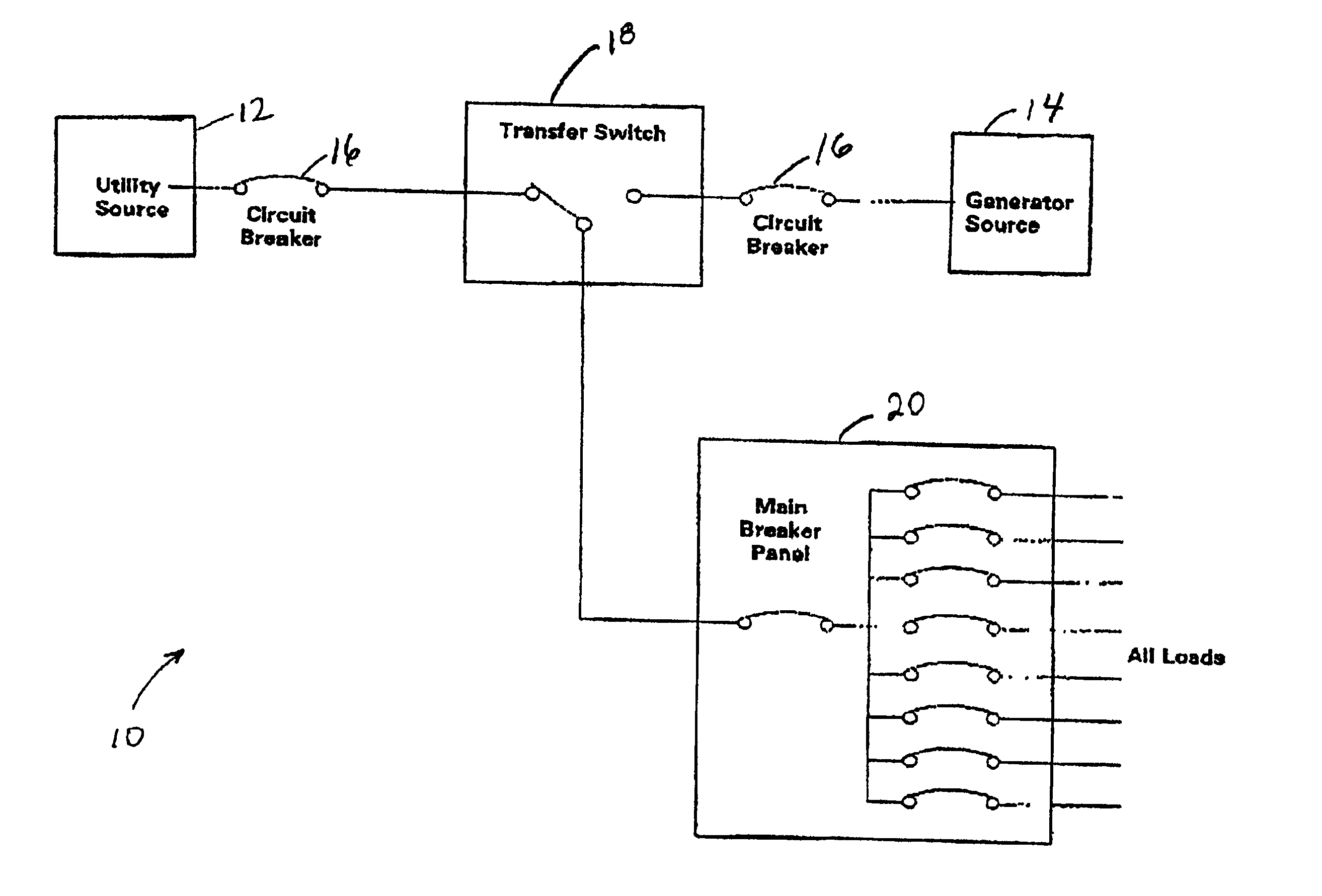
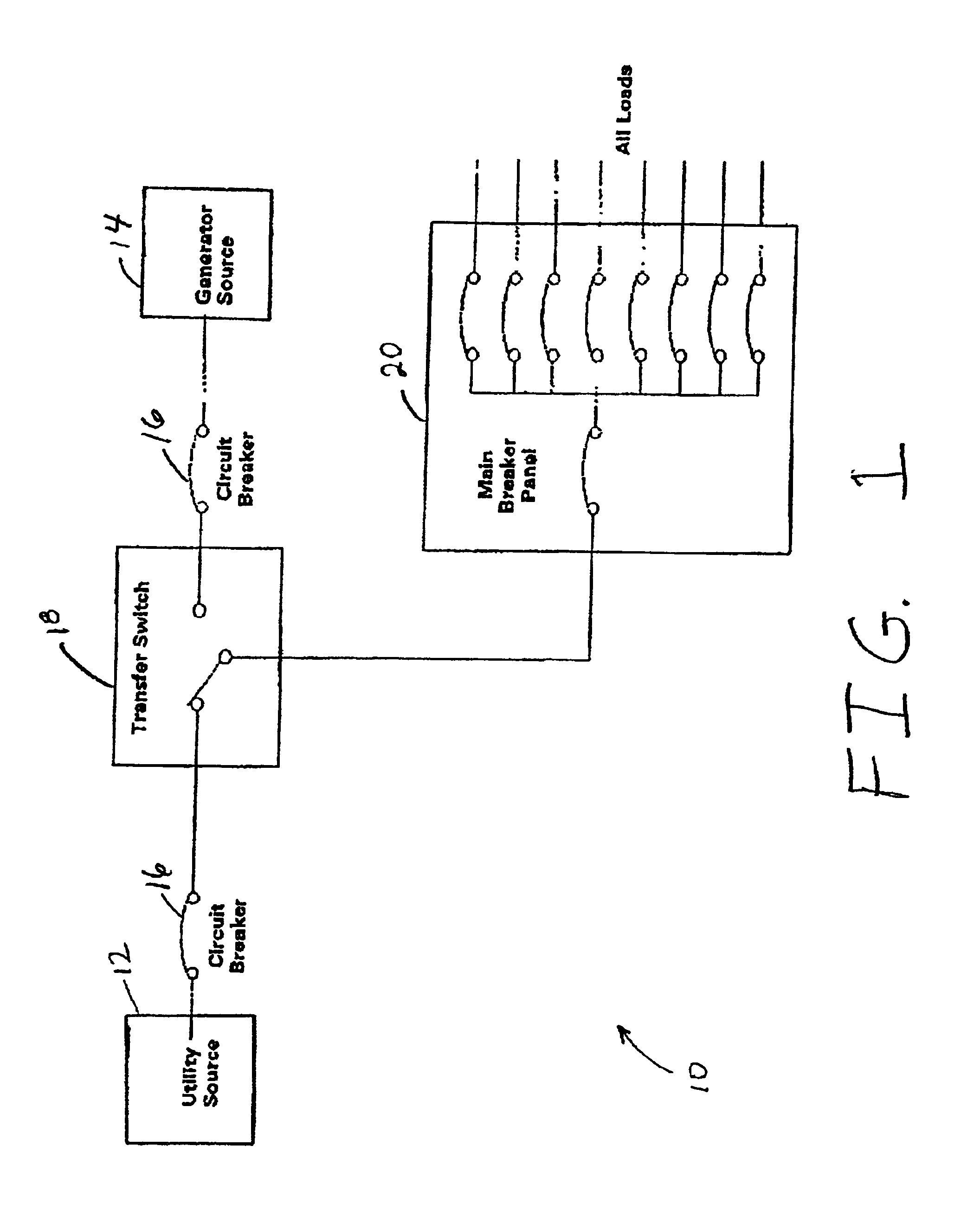
FIG. 1 is a simplified schematic diagram 10 showing electrical routing within an automatic transfer switch (ATS) system. Included in diagram 10 are a utility source 12 and a generator source 14. Each of utility source 12 and generator source 14 are routed through circuit breakers 16 to a transfer switch 18. Transfer switch 18 is configured to route electrical power from utility source 12 through transfer switch 18 to a main breaker panel 20, through which electricity is distributed throughout a facility. Transfer switch 18 is further configured with a controller (not shown) to monitor the power from utility source 12 for power quality, for example voltage, power factor, electrical noise and the like. When the transfer switch controller senses a problem with power quality, based upon preset limits, the transfer switch controller commands transfer switch 18 to switch to electrical power from generator source 14, on a temporary basis, until the transfer switch controller senses that th...


PUM


Abstract

An automatic transfer switch (ATS) controller is disclosed which includes a power supply circuit to regulate and filter input power, a transformer to convert utility and generator power sources into power supply voltages and voltage sensing sources and a voltage sense signal conditioning circuit. Controller further implements a solenoid driver circuit to drive automatic transfer switch solenoids, an embedded microcontroller configured to monitor utility and generator voltages and a user interface interfaced to said microcontroller for operator entry of instructions. A LED indicator is included and is configured to verify user interface entries and overall operation of the controller and ATS system.

Description

BACKGROUND OF THE INVENTIONThis invention relates generally to electrical switches and, more particularly, to automatic transfer switches and control thereof.Many businesses use transfer switches for switching power sources, for example, from a public utility source to a private secondary supply, automatically within a matter of seconds. Critical load businesses, such as, for example, hospitals, airport radar towers, and high volume data centers are dependent upon automatic transfer switches to provide continuous power. Transfer switches typically utilize a plurality of contacts that can be open or closed.Typically, automatic transfer switches are controlled using relay logic, programmable logic controllers (PLCs) or embedded controllers. In known systems, the embedded controller monitors the public utility power source for a fault condition. Upon recognizing any one of a number of faults with the utility power, the embedded controller is configured to switch in the secondary source...

Claims


Application Information

Patent Timeline
Patent Type & Authority Patents(United States)
IPC IPC(8): H02J9/06
CPCH02J9/06
Inventor RADUSEWICZ, PETER J.PAYACK, JR., WALTER PAULKYRK, CARL
Owner GENERAL ELECTRIC CO
Why Eureka
Try Eureka