Tunable resonant cavity

Inactive Publication Date: 2005-04-05
HARRIS CORP
View PDF10 Cites 8 Cited by
  • Summary
  • Abstract
  • Description
  • Claims
  • Application Information

AI Technical Summary

Benefits of technology

The present invention relates to a tunable resonant system, which includes a resonant cavity, and a method for a varying the resonant characteristics of the resonant cavity. The resonant cavity is enclosed by a conductive material and has at least one aperture in the conductive material for coupling the resonant cavity to an RF

Problems solved by technology

Further, the high permittivity, high permeability

Method used


Image

  • Tunable resonant cavity
  • Tunable resonant cavity
  • Tunable resonant cavity

Examples


Embodiment Construction

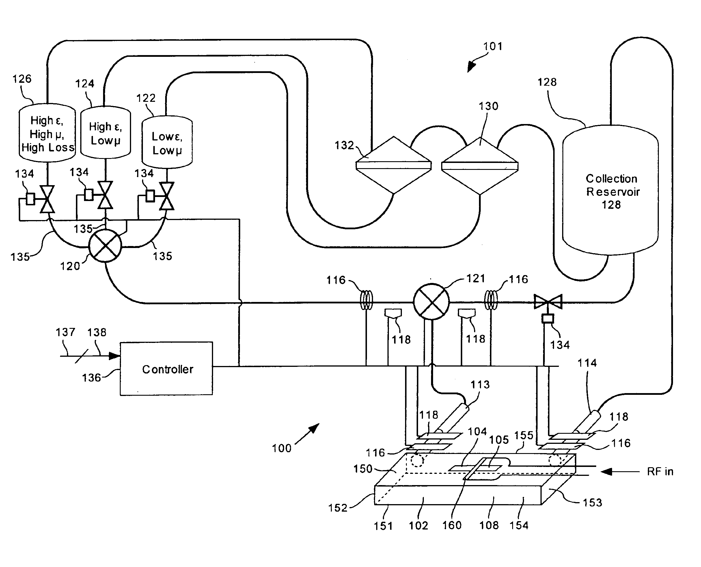
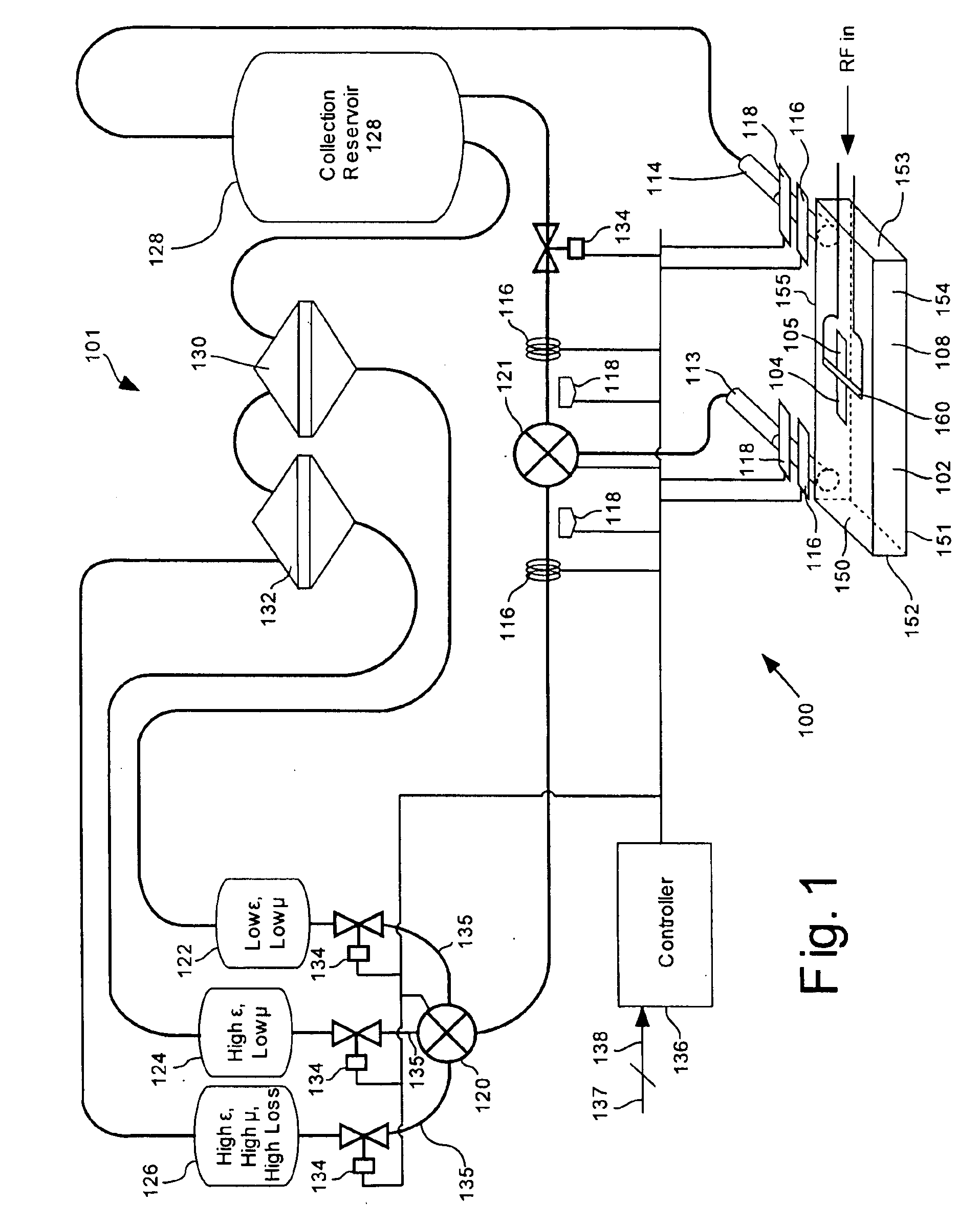
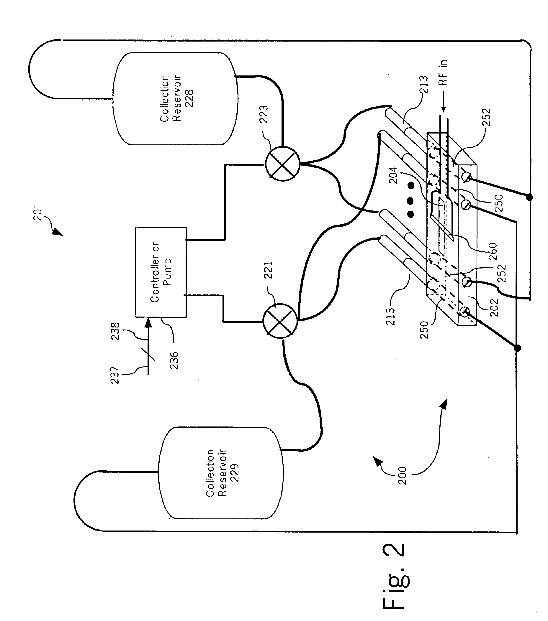
The present invention relates to a tunable resonant system. The invention provides the circuit designer with an added level of flexibility by permitting a fluidic dielectric to be used in a tuned resonant cavity (resonant cavity), thereby enabling the dielectric properties within resonant cavity to be varied. Since group velocity in a medium is inversely proportional to √{square root over (μ∈)}, increasing the permittivity (∈) and / or permeability (μ) in the dielectric decreases group velocity of an electromagnetic field within a resonant cavity, and thus the signal wavelength. Accordingly, the permittivity and permeability of the fluidic dielectric can be selected to decrease the physical size of a resonant cavity and to tune the operational characteristics of the resonant cavity. For example, the permittivity and / or permeability can be adjusted to tune the center frequency of cavity resonances. Further, the loss tangent of the fluidic dielectric can be adjusted in addition to the p...


PUM


Abstract

A tunable resonant system (100) and a method for a varying the resonant characteristics of a resonant cavity (102). The resonant cavity (102) is enclosed by a conductive material that has at least one aperture (104) for coupling the resonant cavity (102) to an RF signal propagating in a circuit device (160). A fluidic dielectric (108) having at least one among a permittivity, a permeability and a loss tangent is at least partially disposed within the resonant cavity (102). A dielectric barrier (105) can be provided within the aperture to prevent fluid (108) from escaping the resonant cavity. A composition processor (101) is adapted for dynamically changing a composition or volume of the fluidic dielectric to vary at least one among the permittivity, the permeability and/or the loss tangent to vary, or maintain constant, a center frequency, a bandwidth, a quality factor (Q) or an impedance of the resonant cavity (102).

Description

BACKGROUND OF THE INVENTION1. Statement of the Technical FieldThe inventive arrangements relate generally to methods and apparatus for providing increased design flexibility for RF circuits and, more particularly, to resonant cavities.2. Description of the Related ArtResonant cavities are well known radio frequency (RF) devices and are commonly used in a variety of RF circuits, for example, in conjunction with microwave antennas and local oscillators. Resonant cavities are typically completely enclosed by conducting walls that can contain oscillating electromagnetic fields. An aperture is generally provided in one of the resonant cavity walls through which RF energy can be transmitted into, and extracted from, the resonant cavity. Resonant cavities can be constructed with a variety of shapes and can be used for different applications and frequency ranges. Nonetheless, the basic principles of operation are the same for all resonant cavities.A resonant cavity resonates at frequencies ...

Claims


Application Information

Patent Timeline
IPC IPC(8): H01P7/00H01P7/06
CPCH01P7/065
Inventor RAWNICK, JAMES J.BROWN, STEPHEN B.
Owner HARRIS CORP
Why Eureka
Try Eureka