Small controlled parasitic antenna system and method for controlling same to optimally improve signal quality

a parasitic antenna and small-scale technology, applied in the direction of resonant antennas, individually energised antenna arrays, non-resonant long antennas, etc., can solve the problems of affecting much more antenna multifunctionality, and achieve the effect of minimizing or maximizing some metric of the received output of the antenna, and reducing the adverse impact of interferen

Inactive Publication Date: 2005-04-05
TOYON RES CORP
View PDF41 Cites 94 Cited by
  • Summary
  • Abstract
  • Description
  • Claims
  • Application Information

AI Technical Summary

Benefits of technology

The present invention provides an adaptive capability for mitigating the adverse impact of interference or jamming (hostile interference) to communication systems. Unlike, the “smart” antenna concept, it avoids the three drawbacks mentioned above. In particular it uses a single antenna output port and has an aperture whose largest dimension is about one-half wavelength or less. It too makes use of a digital signal processor. However, it provides interference control not by means of multiple sets of output weights but rather by adaptively setting the biases applied to active circuits in the antenna aperture. These circuits are attached to parasitic elements that are contained within the radiating aperture. The variable impedances of these circuits act in a manner that is analogous to processor weights. However, they are applied in the RF front end where they can affect much more antenna multifunctionality than is possible with conventional “smart” antenna concepts. The processor in this invention is actually part of a feedback and control loop that adapts the impedance circuits to minimize or maximize some metric of the received output from the antenna. This antenna system design can also be used to provide tuning control of the antenna element. This provides the possibility of operating over a larger frequency range than is typically the case in conventional antenna system designs.

Problems solved by technology

However, they are applied in the RF front end where they can affect much more antenna multifunctionality than is possible with conventional “smart” antenna concepts.

Method used


Image

  • Small controlled parasitic antenna system and method for controlling same to optimally improve signal quality
  • Small controlled parasitic antenna system and method for controlling same to optimally improve signal quality
  • Small controlled parasitic antenna system and method for controlling same to optimally improve signal quality

Examples


Embodiment Construction

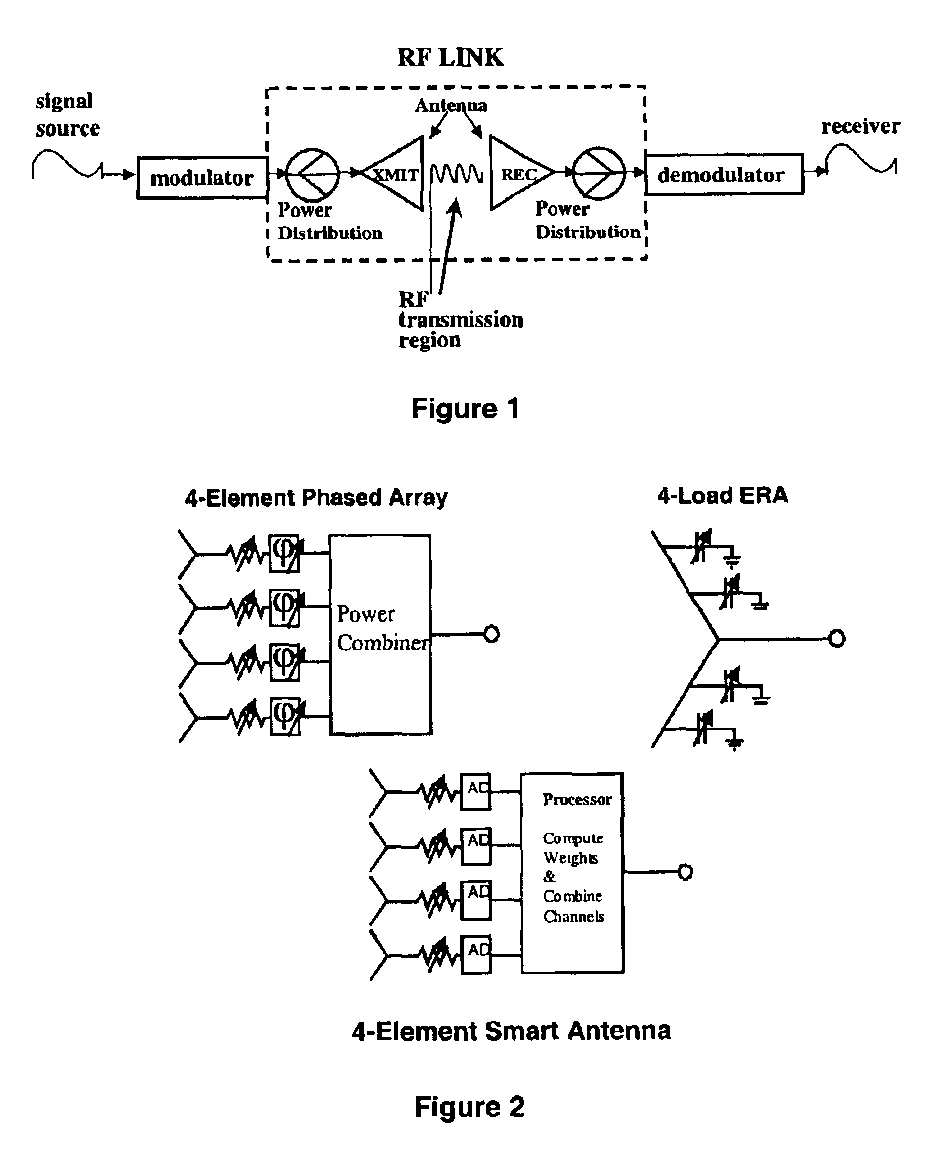
As a background to the invention, the manner in which the RF properties of CPA devices can be controlled will now be described. In the context of this specification RF refers to the frequency (or range of frequencies) of a transmission which propagates through space. Also described herein is how the function of the CPA differs from conventional and other state of the art approaches to antenna pattern control and interference mitigation. An antenna is an RF device. It is important to emphasize that in a CPA system control and adaptability are applied in the antenna aperture. This is RF control. FIG. 1 is meant to illustrate what is meant by RF control.

FIG. 1 could be applied to any situation involving an RF wireless link. Such applications would include communication between separate points, broadcasting, or radar. A signal waveform is generated by some source and this is used to modulate an RF carrier and so produce a modulated RF waveform. A modulator accomplishes this. This RF wav...


PUM


Abstract

The invention relates to a small (0.5 wavelength or less) adaptable antenna system. In particular it relates to the use of loaded parasitic components in the antenna aperture for the purpose of controlling the RF properties of the antenna. Such an antenna system is here referred to as a controlled parasitic antenna (CPA). Parasitic elements within the radiating aperture are terminated by active (controllable) impedance devices. A feedback and control subsystem periodically adjusts the impedance characteristics of these devices based on some observed metric of the received waveform. Such antenna systems can provide multifunctionality within a single aperture and / or mitigate problems associated with the reception of an interfering signal (or signals) or multi-path effects. Such antenna systems are particularly suitable to a situation where an aperture size is desired that is too small for the use of an adaptive phased array.

Description

TECHNICAL FIELDThe present invention relates in general to the field of small adaptable antenna systems. By ‘small’ is meant an antenna system whose largest dimension is about ½ wavelength or less at the lower end of the operational band. In particular the invention relates to the use of loaded parasitic components within the radiating aperture of an antenna element for the purpose of controlling the RF properties of the antenna element. It also relates to the use of a feedback and control subsystem that is part of the antenna system and which periodically adjusts the RF properties of the parasitic components based on some observed metric of the received waveform. This small antenna system will be referred to as a controlled parasitic antenna (CPA). By using a feedback subsystem to control the electromagnetic properties of the antenna aperture, this antenna system can provide multifunctionality and / or mitigate problems associated with the reception of an interfering signal (or signa...

Claims


Application Information

Patent Timeline
Patent Type & Authority Patents(United States)
IPC IPC(8): H01Q1/36H01Q11/08H01Q3/26H01Q11/00
CPCH01Q11/08H01Q3/267H01Q1/36
Inventor LARRY, THOMAS
Owner TOYON RES CORP
Why Eureka
Try Eureka