Rangefinder for obtaining information from a three-dimensional object

a three-dimensional object and rangefinder technology, applied in the field of rangefinders, can solve the problems of user inability to obtain precise range information, taking too much time and trouble, and inability to effectively control the optical output power, and achieve the effect of high-precision information

Inactive Publication Date: 2005-04-05
PANASONIC CORP
View PDF10 Cites 61 Cited by
  • Summary
  • Abstract
  • Description
  • Claims
  • Application Information

AI Technical Summary

Benefits of technology

An objective of the present invention is providing a rangefinder that can always obtain highly precise information about the 3D location of an object without doing any harm on the object.

Problems solved by technology

Firstly, in the conventional rangefinder, the optical output power of the light source section 10 is supposed to be adjusted by the user. In fact, the power has been adjusted appropriately through the user's experience or by his or her trial and error. In other words, if a beginner should handle such a rangefinder, it is usually difficult for him or her to control the optical output power effectively. As a result, the user cannot always obtain precise range information.
Secondly, if the object is on the move, then the optical output power should be re-adjusted for every movement of the object, thus taking too much time and trouble.
Thirdly, supposing the output power is set too high while the object is located very close to the rangefinder, some harm might be done on the object.
Moreover, the known rangefinder has additional problems. FIG. 25 illustrates the signal levels of a video signal during a 3D imaging process.
However, since the dynamic range of the camera section 20 is predefined, the signal level LA of the reflected light component cannot be increased above a certain maximum acceptable level.
Accordingly, the signal-to-noise ratio of the object cannot be increased sufficiently, thus interfering with the precision improvement of the 3D location information.

Method used


Image

  • Rangefinder for obtaining information from a three-dimensional object
  • Rangefinder for obtaining information from a three-dimensional object
  • Rangefinder for obtaining information from a three-dimensional object

Examples


embodiment 1

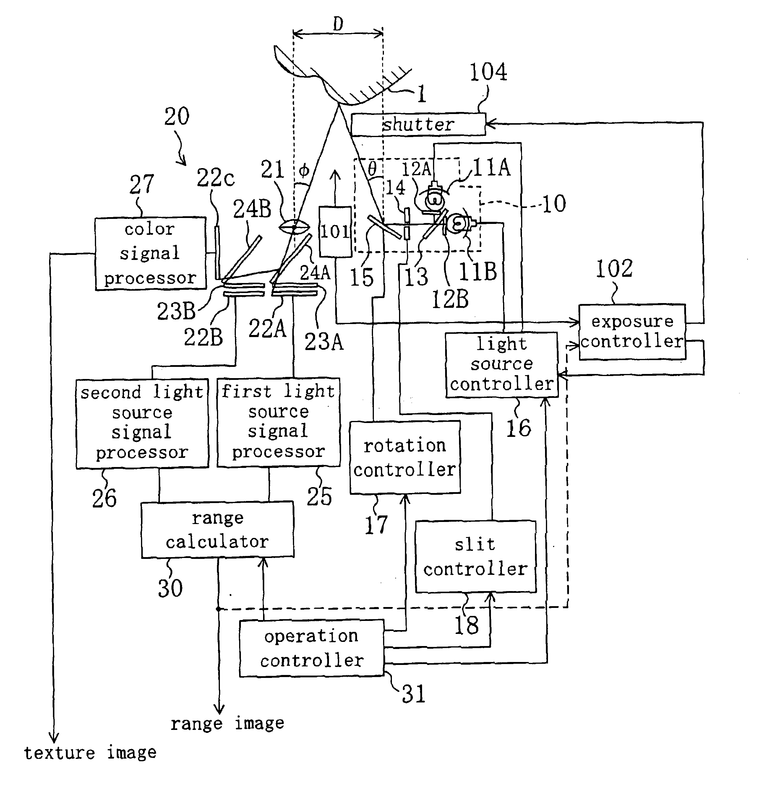
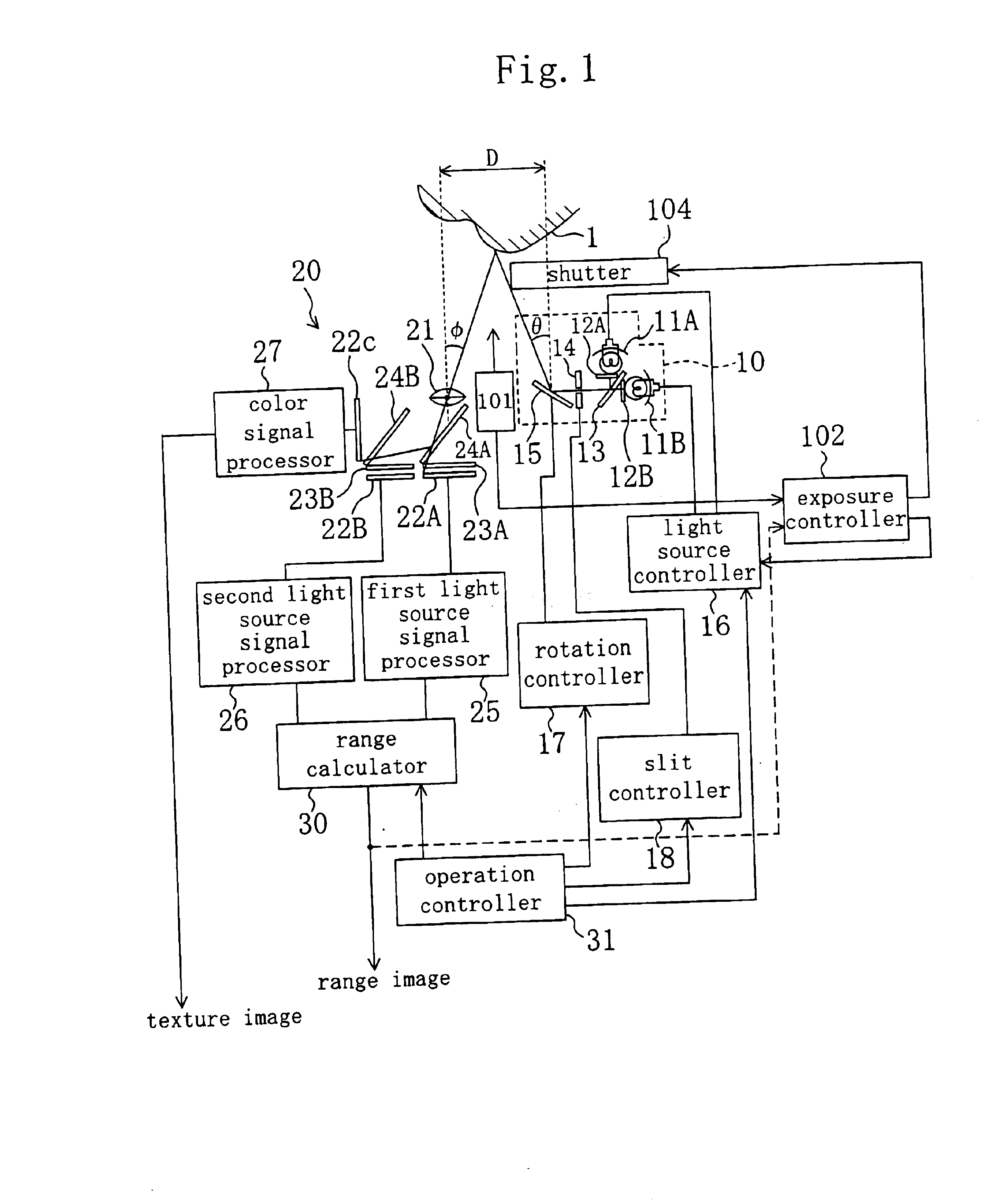
FIG. 1 illustrates a configuration for a rangefinder according to a first exemplary embodiment of the present invention. In FIG. 1, the same members as those included in the prior art rangefinder shown in FIG. 22 are identified by the same reference numerals and the detailed description thereof will be omitted herein.

As shown in FIG. 1, the rangefinder includes a distance-measuring sensor 101 for estimating an approximate averaged distance from the rangefinder to an object 1. The distance-measuring sensor 101 is implementable as a sensor of the type detecting ultrasonic waves reflected from the object 1. The rangefinder also includes an exposure controller 102, which is equivalent to the controller as defined in the appended claims. Based on range information provided from the distance-measuring sensor 101, the exposure controller 102 controls the operations of a light source controller 16 and a shutter 104. As in the known rangefinder, the light source controller 16 controls the op...

embodiment 2

FIG. 5 illustrates a configuration for a rangefinder according to a second embodiment of the present invention. In FIG. 5, the same members as those included in the prior art rangefinder shown in FIG. 22 are identified by the same reference numerals and the detailed description thereof will be omitted herein. In the rangefinder shown in FIG. 5, light is also projected from a light source section 10 and part of the light that has been reflected from an object 1 is also received at a camera section 310, thereby obtaining information about the 3D location of the object 1. According to the second embodiment, the camera section 310 can capture a color image (i.e., a 2D image), too. The 3D location information is obtained by the known technique.

The camera section 310 includes a lens 312, a diaphragm 313, an imager (CCD) 314 and a neutral density (ND) filter 311, which is disposed in front of the lens 312. The ND filter 311 includes a liquid crystal device. The transmittance of the ND filt...

embodiment 3

FIG. 11 illustrates a configuration for a videophone system including an imager according to a third exemplary embodiment of the present invention. In FIG. 11, the same members as those included in the rangefinder shown in FIG. 5 are identified by the same reference numerals and the detailed description thereof will be omitted herein. In this case, an object 711 is a human face.

FIG. 12(a) illustrates how the imager shown in FIG. 11 performs time-sharing processing. As shown in FIG. 12(a), first and second intervals T1 and T2 alternate according to this embodiment. In the first interval T1, an infrared flash lamp 701a is lit and the image captured is divided into foreground and background parts based on the reflected part of the light. In the second interval T2, a color image (i.e., a 2D image) is captured and only the foreground part is separated from the image.

As shown in FIG. 11, a light source section 701 includes the infrared flash lamp 701a and a transmission liquid crystal dis...


PUM


Abstract

A rangefinder according to the present invention includes light source section, camera section, distance-measuring sensor, exposure controller and shutter. The light source section projects light onto an object for 3D imaging purposes. The camera section receives the light that was emitted from the light source section and then reflected from the object. The distance-measuring sensor estimates an approximate distance to the object. Based on the approximate distance, the exposure controller controls the optical output power of the light source section and/or the open/closed states of the shutter. The rangefinder can control the intensity of the projected light even if the object is on the move. As a result, the rangefinder can obtain highly precise information about the 3D location of the object.

Description

BACKGROUND OF THE INVENTIONThe present invention relates to a rangefinder for obtaining information about the three-dimensional (3D) location of an object and also relates to an imager.FIG. 22 illustrates an exemplary configuration for a prior art rangefinder. As shown in FIG. 22, a light source section 10 includes first and second light sources 11A and 11B. Filters 12A and 12B are disposed in front of the light-emitting ends of the light sources 11A and 11B, respectively. The light beams that have been emitted from the first and second light sources 11A and 11B are combined into a single beam at a half mirror 13. Then, the combined beam is projected onto an object 1 after having passed through a slit 14 and a rotating mirror 15. The output wavelengths of the light sources 11A and 11B are defined within the infrared range of the spectrum.FIGS. 23(a) and 23(b) illustrate exemplary characteristics of the filters 12A and 12B. As shown in FIG. 23(a), the filters 12A and 12B may selectiv...

Claims


Application Information

Patent Timeline
Patent Type & Authority Patents(United States)
IPC IPC(8): G01S17/89G01S17/00G01S17/42G01S7/48G01S7/484G01S7/481H04N5/235G01B11/24
CPCG01S7/481G01S7/484H04N5/2354G01S17/89H04N5/2352G01S17/42H04N23/72H04N23/74G01B11/24
Inventor UOMORI, KENYAAZUMA, TAKEONOBORI, KUNIOMORIMURA, ATSUSHI
Owner PANASONIC CORP
Why Eureka
Try Eureka