

Color-stabilized electrochromic devices
- Summary
- Abstract
- Description
- Claims
- Application Information
AI Technical Summary
Benefits of technology
Problems solved by technology
Method used
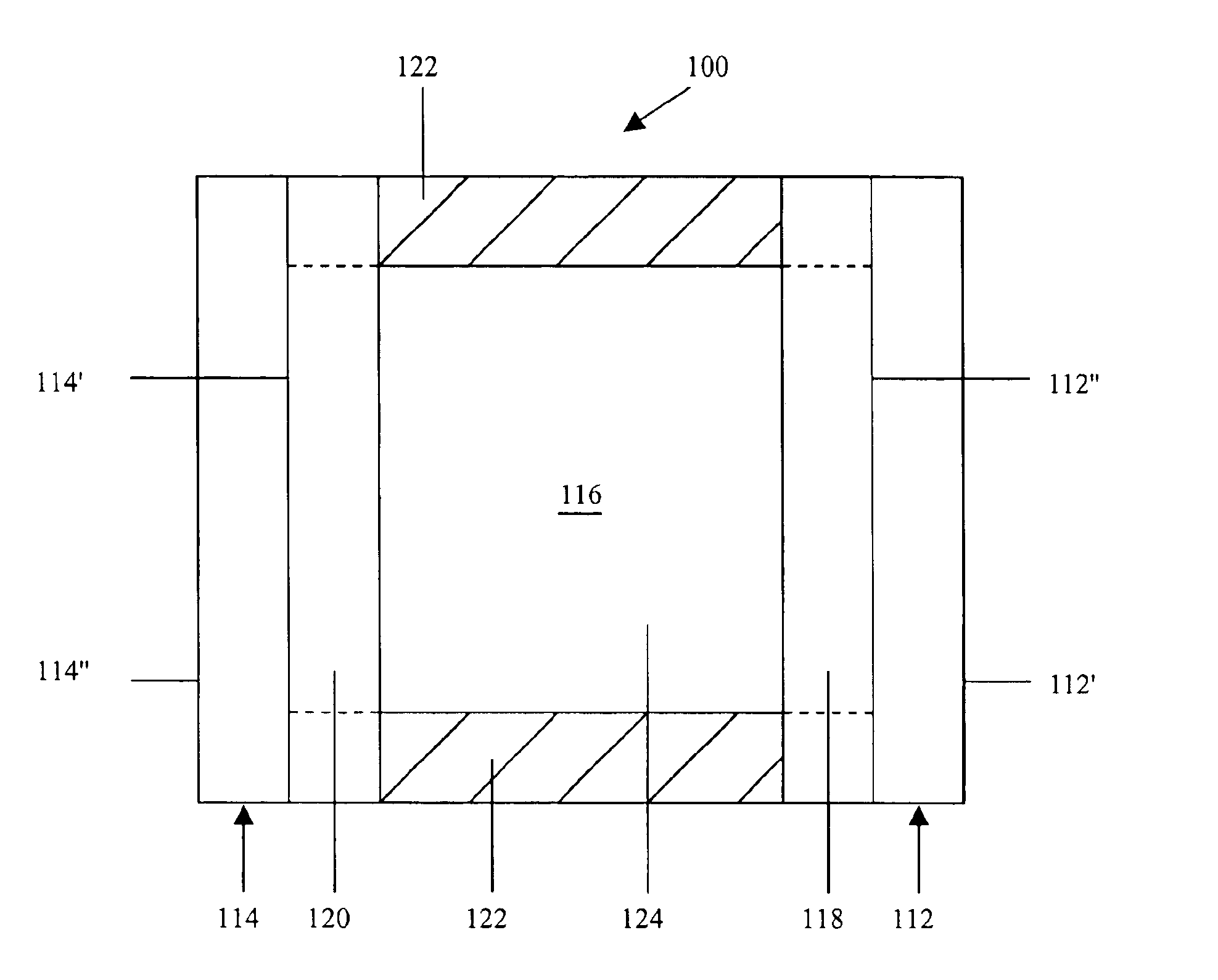
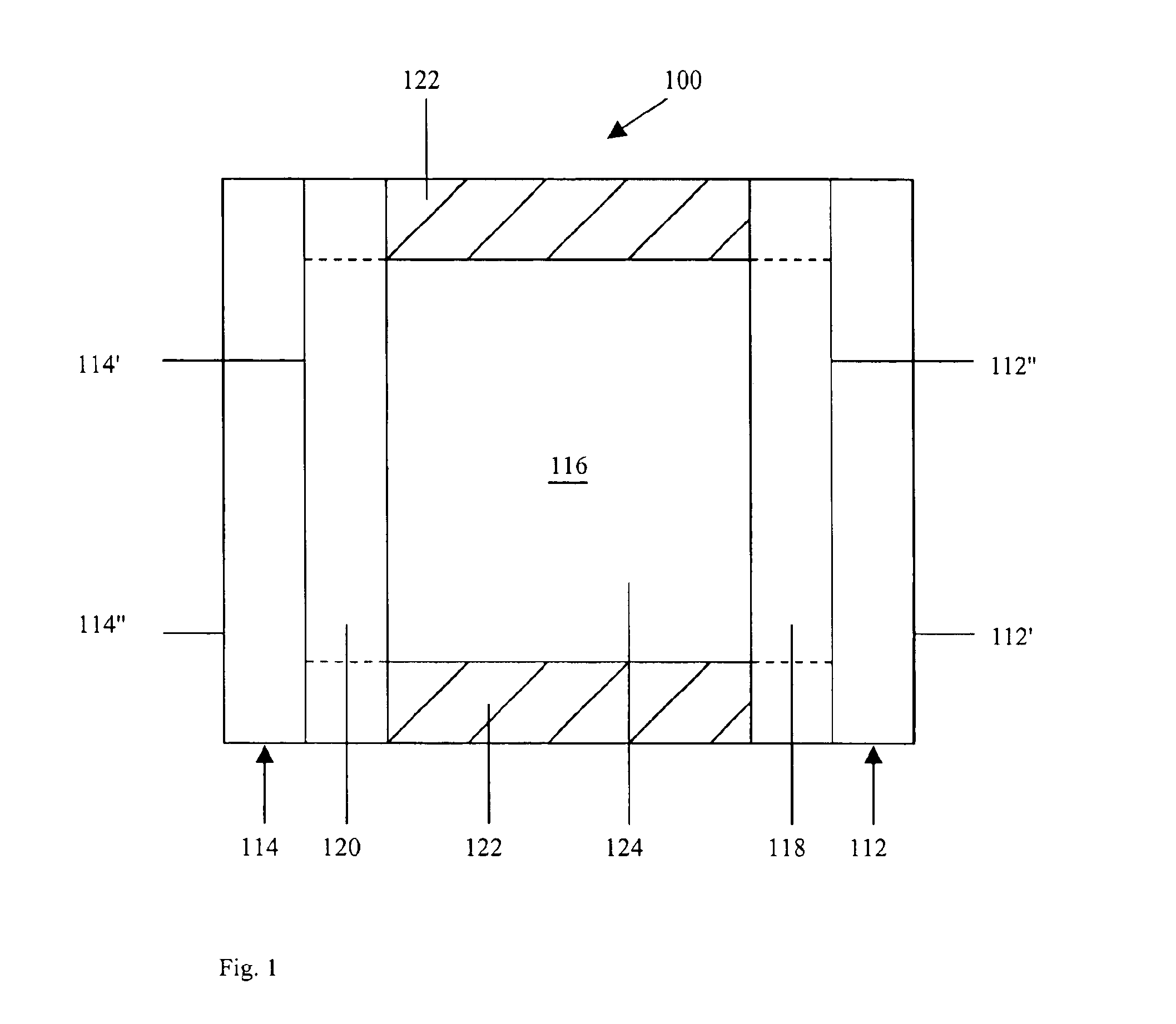
Image

Examples
first embodiment
In the invention, the additive is more easily reduced than the cathodic material, and, during normal operation of the electrochromic device, serves to substantially preclude the formation of a residual reduced cathodic material while the device is in its high transmission state. The term “high transmission state” is defined as the bleached state, the unpowered state, the unactivated state and / or the open circuit state of the electrochromic device, or a state where it is desirous for the electrochromic medium within the device to be colorless or nearly colorless. As previously discussed, a residual reduced cathodic material can form from any one of a number of different reasons, and can leave the electrochromic medium undesirably tinted or colored, when it is desirous for the electrochromic medium to be colorless or nearly colorless.
In this first embodiment of the invention, the additive may comprise an oxidized form of the anodic material, or alternatively, the additive may comprise...
second embodiment
In the invention, the additive comprises a reduced form of the cathodic material, and, during normal operation of the electrochromic device, serves to substantially preclude the formation of a residual oxidized anodic material while the device is in its high transmission state. Examples of suitable cathodic materials and their associated reduced species may include, for example, those identified below:
Cathodic MaterialAdditive[Ru(NH3)6]3+[Ru(NH3)6]2+[Fe(CN)6]3−[Fe(CN)6]4−[Cr(bpy*)3]3+[Cr(bpy*)3]2+[PMo12O40**]3−[PMo12O40**]4−*wherein bpy is a bipyridine based ligand **wherein PMo12O40 is a polyoxometalate complex
It will be understood that only the electrochemically relevant portion of the complexes have been disclosed and that the above-identified complexes can be associated with any one of a number of cations or anions to form a neutral species. Preferably the concentration of the additive ranges from approximately 0.01 mM to approximately 10 mM.
In a third embodiment of the inventi...
fourth embodiment
In the invention, the additive comprises a first component that is more easily reduced than the cathodic material and a second component that is more easily oxidized than the anodic material. During normal operation of the electrochromic device, the first component serves to substantially preclude the formation of a residual reduced cathodic material and the second component serves to substantially preclude the formation of a residual oxidized anodic material while the device is in its high transmission state.
The first additive component may comprise either an oxidized form of the anodic material, or an additional electroactive material present in an oxidized form—or both with appropriate control of additive stoichiometry. Examples of suitable first components include ferrocinium salts, substituted ferrocinium salts, phenazinium salts, and substituted phenazinium salts. Specific materials may include, for example, di-tert-butyl-diethylferrocinium tetrafluoroborate, (6-(tetra-tert-bu...
PUM
 Abstract
Description
Claims
Application Information