Delay and channel estimation for multi-carrier CDMA system

a cdma system and delay technology, applied in the field of decoding signals received by receivers, can solve problems such as limiting the data rate of transmission

Inactive Publication Date: 2005-04-05
ERICSSON INC
View PDF10 Cites 45 Cited by
  • Summary
  • Abstract
  • Description
  • Claims
  • Application Information

AI Technical Summary

Problems solved by technology

However, this can limi...

Method used


Image

  • Delay and channel estimation for multi-carrier CDMA system
  • Delay and channel estimation for multi-carrier CDMA system
  • Delay and channel estimation for multi-carrier CDMA system

Examples


Embodiment Construction

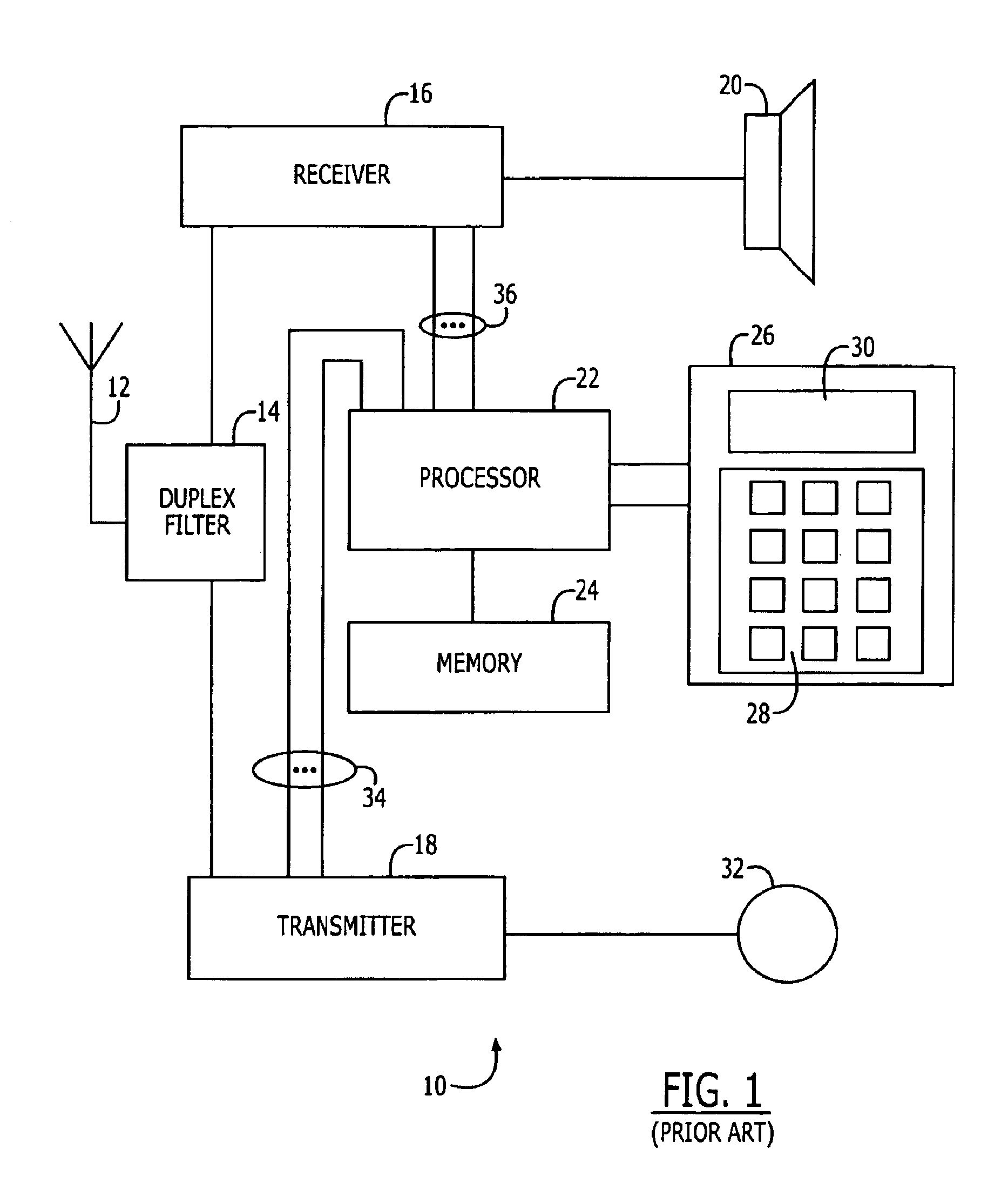
FIG. 1 is a block diagram of a mobile terminal shown generally at 10. The mobile terminal 10 includes an antenna 12, a receiver 16, a transmitter 18, a speaker 20, a processor 22, a memory 24 a user interface 26 and a microphone 32. The antenna 12 is configured to send and receive radio signals between the mobile terminal 10 and a wireless network (not shown). The antenna 12 is connected to a duplex filter 14 which enables the receiver 16 and the transmitter 18 to receive and broadcast (respectively) on the same antenna 12. The receiver 16 demodulates, demultiplexes and decodes the radio signals into one or more channels Such channels include a control channel and a traffic channel for speech or data. The speech or data are delivered to the speaker 20 (or other output device, such as a modem or fax connector).

The receiver 16 delivers messages from the control channel to the processor 22. The processor 22 controls and coordinates the functioning of the mobile terminal 10 responsive t...


PUM


Abstract

A receiver for a multi-carrier CDMA system receives a signal transmitted having a known pilot sequence on plural sub-carriers. The system includes plural down-converters for down-converting the received signal to baseband signals. A delay and channel estimator correlates at least one of the baseband signals with a single wideband pilot signal, the single wideband pilot signal including all of the known pilot sequences, to produce an estimate of channel gain and multi-path delay. Plural demodulators, one for each of the plural sub carriers, are operatively coupled to the delay and channel estimator, each for demodulating one of the plural baseband signals using the estimate of channel gain and multi-path delay.

Description

BACKGROUND OF THE INVENTIONThis invention relates to receivers for decoding signals received via multiple propagation paths having different propagation delays and, more particularly, to delay and channel estimation for multi-carrier systems.Radio receivers are often used for decoding fading signals with the aid of estimates of the instantaneous propagation channel phase and amplitude characteristics. An exemplary application for such a radio receiver is a cellular phone for decoding signals transmitted by base stations using code division multiple access (CDMA) protocols.A radio receiver, such as for a CDMA system, receives digitally coded and modulated signals from a transmitter. These signals include known, preselect signal patterns at known time intervals. Using known signal patterns, also referred to as pilot sequences, or pilot channel as commonly used in the CDMA literature, the receiver forms successive estimates of the delay and amplitude or complex value of propagation pat...

Claims


Application Information

Patent Timeline
IPC IPC(8): H04B1/707H04L27/26H04L5/02H04B1/711H04B1/712
CPCH04B1/711H04L5/026H04L27/2657H04B1/712
Inventor GUEY, JIANN-CHINGSOUROUR, ESSAM
Owner ERICSSON INC
Why Eureka
Try Eureka