Method and system for radio wave propagation characteristics estimation and ray spatial resolution control

a radio wave propagation characteristic and estimation method technology, applied in the field of radio wave propagation characteristics estimation and ray spatial resolution control, can solve the problems of degrading overall estimation accuracy and increasing the calculation time taken for radio wave propagation estimation, so as to improve the estimation accuracy of radio wave propagation characteristics, shorten the total calculation time taken for propagation estimation, and improve the effect of estimation accuracy

Inactive Publication Date: 2005-04-05
NEC CORP
View PDF0 Cites 3 Cited by
  • Summary
  • Abstract
  • Description
  • Claims
  • Application Information

AI Technical Summary

Benefits of technology

The operation of the invention will be set forth below. In the invention, when a ray is propagated within a given observation area, and collides with a barrier residing on its path, a space in the vicinity of the ray is divided into a plurality of partial spaces until a predetermined condition is satisfied. With the conventional method, the partial space was divided in accordance with the propagation distance, irrespective of the reflection. However, with the inventive method, the partial space that is considered to cause a degradation in the estimation precision if dealt with uniformly is divided until there is less influence of degradation, whereby each of the subdivided partial spaces can be handled individually. Employing this inventive method, the estimation precision of radio wave propagation characteristics

Problems solved by technology

However, to improve the estimation precision, if the upper limit value of the entire spatial resolution is set at the minimum value of spatial resolution required when reflecting the ray from the barrier, there is a problem that the calculation time taken for the ra

Method used


Image

  • Method and system for radio wave propagation characteristics estimation and ray spatial resolution control
  • Method and system for radio wave propagation characteristics estimation and ray spatial resolution control
  • Method and system for radio wave propagation characteristics estimation and ray spatial resolution control

Examples


second embodiment

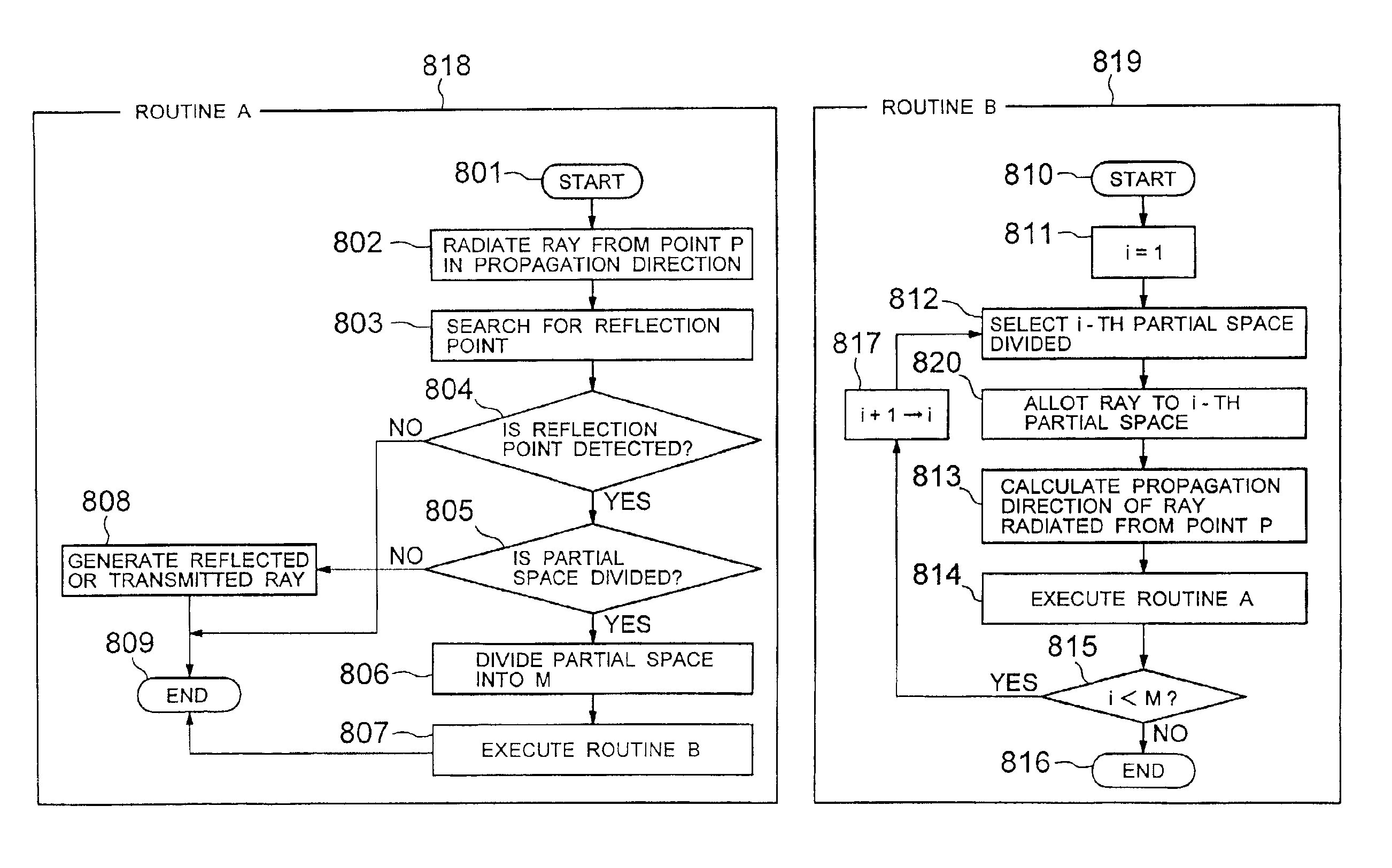
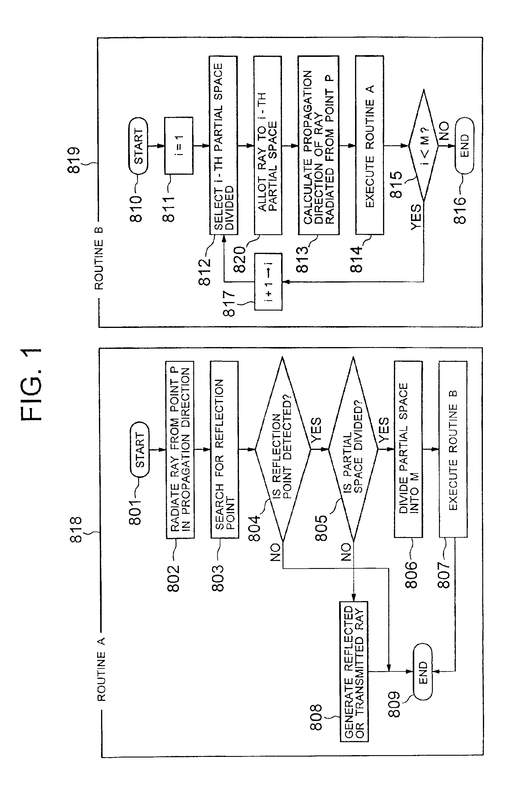
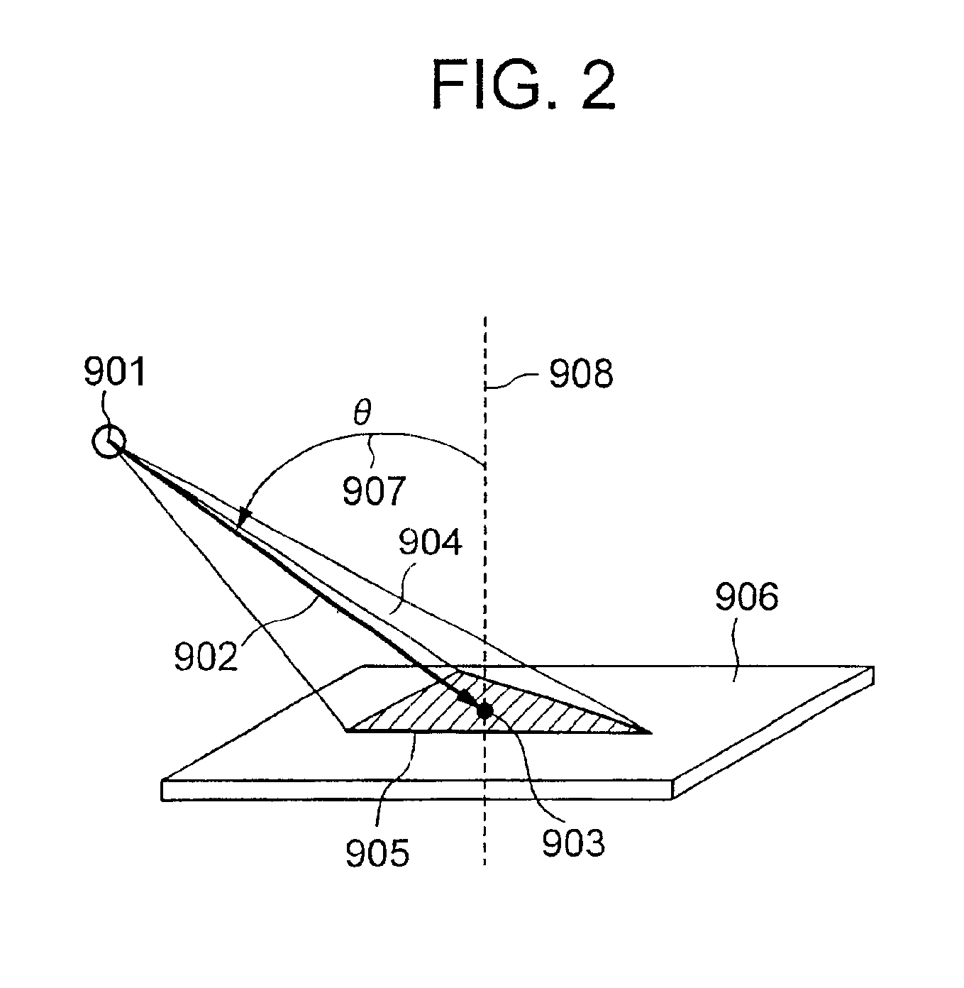
the invention will be described below by reference to the drawings. In the first embodiment, the space around the antenna is divided by the conical form so that the partial space is severed by a plane perpendicular to the ray as shown in FIG. 4. On the other hand, in the second embodiment, the space around the antenna is divided so that the partial space is severed as shown in FIG. 8. In FIG. 8, an instance of M=7 where the partial space is subdivided into similar regular hexagons 1409 to 1415 of a regular hexagon 1408 is shown. The regular hexagons 1409 to 1414 are contact with the vertexes of the regular hexagon 1408 at the middle points 1416 to 1421 of their sides, and after division, the ray allotted to the partial spaces pass through the centers of gravity 1401 to 1407 for the regular hexagons 1409 to 1415.

In the case where a relatively circular figure is employed like the regular hexagon used in this second embodiment, a determination whether or not the ray is taken in when th...


PUM


Abstract

To shorten a required estimation time while keeping an estimation precision in an object environment given for estimating propagation characteristics with a ray launching method. In the case where a ray is propagated within a given observation area, and collides with a barrier residing on its path, a space in the vicinity of the ray is divided into a plurality of partial spaces until a predetermined condition is satisfied. The space in the vicinity of the ray that is considered to cause a degradation in the estimation precision is divided in reflection until there is less influence of degradation, whereby each of the subdivided partial spaces can be handled individually, so that the estimation precision of radio wave propagation characteristics can be made better than a conventional method. On the other hand, in the case where there is possibly less influence of degradation in the estimation precision, the space is not divided, whereby if a ray is radiated from a transmitting antenna coarsely, the total number of rays is reduced below that of the conventional method, so that a total calculation time taken for a propagation estimation can be shortened.

Description

BACKGROUND OF THE INVENTION1. Field of the InventionThe present invention relates to a method and a system for a radio wave propagation characteristics estimation and a ray spatial resolution control, and in particular to a radio wave propagation characteristics estimation method, and a ray spatial resolution control method in predicting the radio wave propagation characteristics by a technique of geometrical optics.2. Description of the Prior ArtA radio wave propagation simulator is employed to assist the arrangement of a base station or a host system in a radio communication system. The received power or delay spreading at any receiving point can be estimated by using the radio wave propagation simulator. On the basis of this estimation, an installation site of an effective transmitting station is determined, so that the overall efficiency can be enhanced by reducing the number of base stations to be arranged.The radio wave propagation simulation is largely classified into a stati...

Claims


Application Information

Patent Timeline
IPC IPC(8): H04Q7/36G01R29/08G01R29/10H04W16/18
CPCH04W16/18
Inventor WATANABE, YOSHINORIFURUKAWA, HIROSHI
Owner NEC CORP
Why Eureka
Try Eureka