

Mobile communication system using loss cables as transmission elements
- Summary
- Abstract
- Description
- Claims
- Application Information
AI Technical Summary
Benefits of technology
Problems solved by technology
Method used
Image

Examples
Embodiment Construction
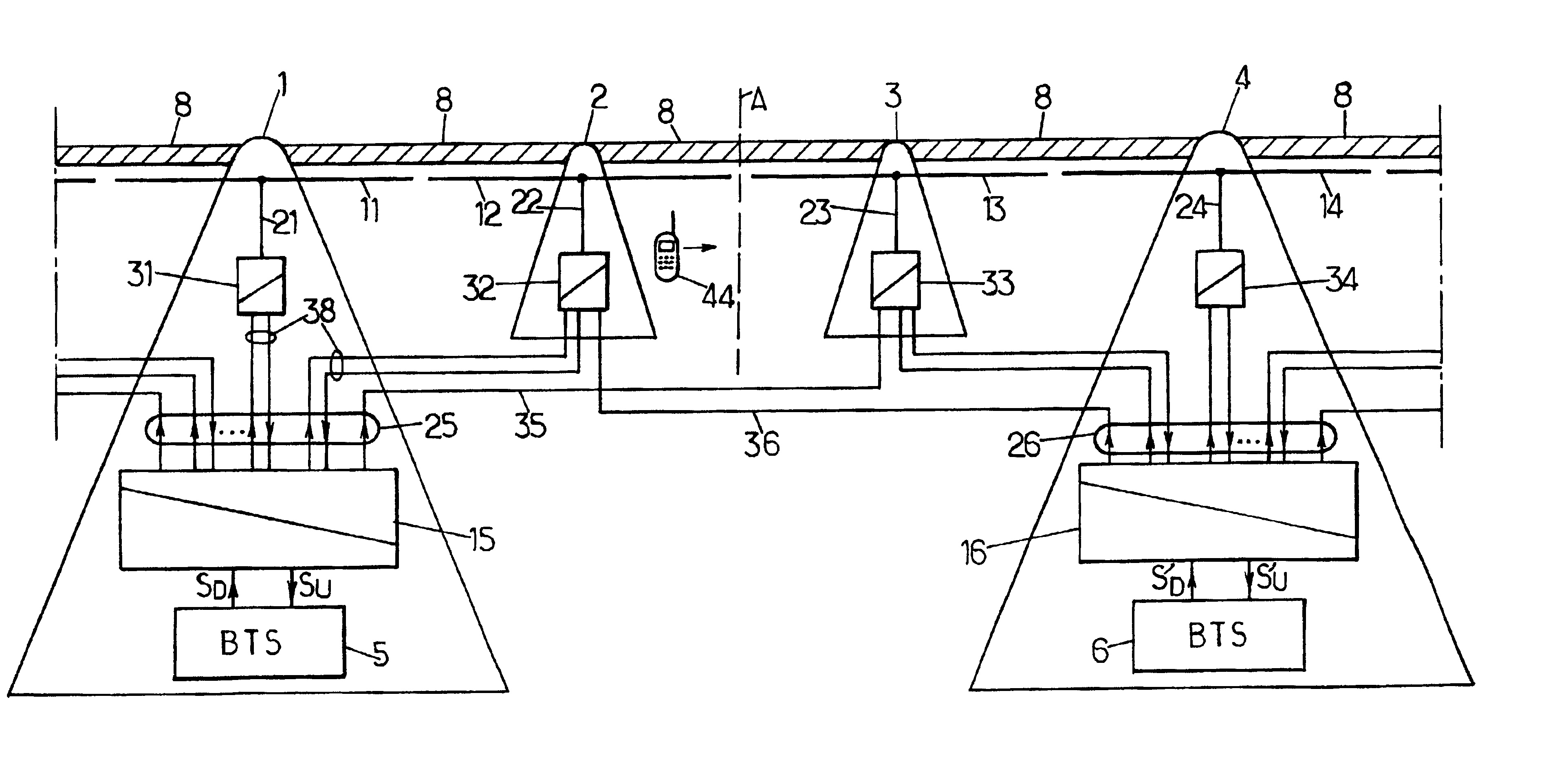
[0020]FIG. 1 schematically illustrates deployment of a cellular mobile communication network along an underground railway line having stations 1-4 separated by tunnels 8.
[0021]Base stations (BTS) of the cellular network are disposed in some of the stations 1, 4. The antennas of these base stations 5, 6 are provided in the form of runs of loss cable 11-14 arranged one after the other along the railway systems in order to provide radio coverage inside the tunnels 8. For example, they are suspended from the roof of the tunnels 8. Each BTS 5, 6 may cooperate with several runs of loss cable, 11-12 and 13-14 respectively. The cell serviced by this BTS 5, 6 corresponds to the radio coverage zone of the different cable runs co-operating therewith. In the illustration provided in FIG. 1, line A diagrammatically represents the boundary between the cells serviced by the BTS 5 and 6 respectively.
[0022]The radio stage of each BTS 5, 6 is linked to a RF / FO coupler-multiplexer 15, 16 which acts as...
PUM
 Abstract
Description
Claims
Application Information