Nozzle assembly with flow divider and ecology valve

a technology of flow divider and ecology valve, which is applied in the direction of combustion types, bends, lighting and heating apparatus, etc., can solve the problems of premature failure of the nozzle, affecting the performance of the engine, and inability to meet the needs of us

Inactive Publication Date: 2005-04-12
WOODWARD GOVERNOR CO
View PDF14 Cites 39 Cited by
  • Summary
  • Abstract
  • Description
  • Claims
  • Application Information

AI Technical Summary

Benefits of technology

In one embodiment, each retention passage includes a spiral section winding axially about an axis between spiral end portions. A nozzle passage is connected to the one of the spiral end portions and extends axially toward the other spiral end portion to prevent drainage of the liquid from a cavity in the valve that is connected to the other spiral end portions.

Problems solved by technology

This hinders engine performance and leads to premature failure of the nozzle.
The removal of fuel also keeps the fuel from vaporizing into the atmosphere, which is not acceptable from an environmental standpoint.
For small engines this is only a small weight and cost penalty.
However, these flow divider valves do not provide the ecology function.

Method used


Image

  • Nozzle assembly with flow divider and ecology valve
  • Nozzle assembly with flow divider and ecology valve
  • Nozzle assembly with flow divider and ecology valve

Examples


Embodiment Construction

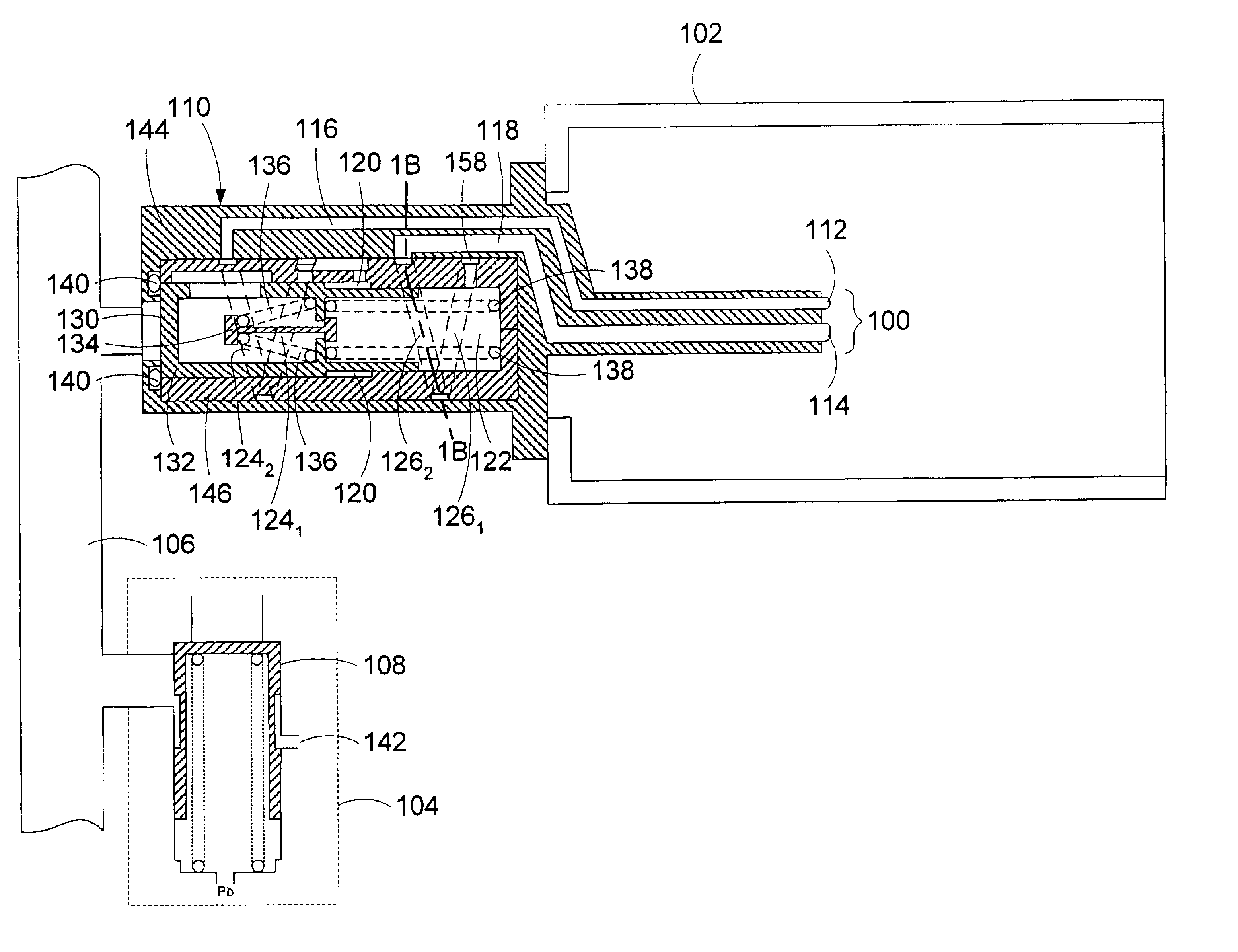
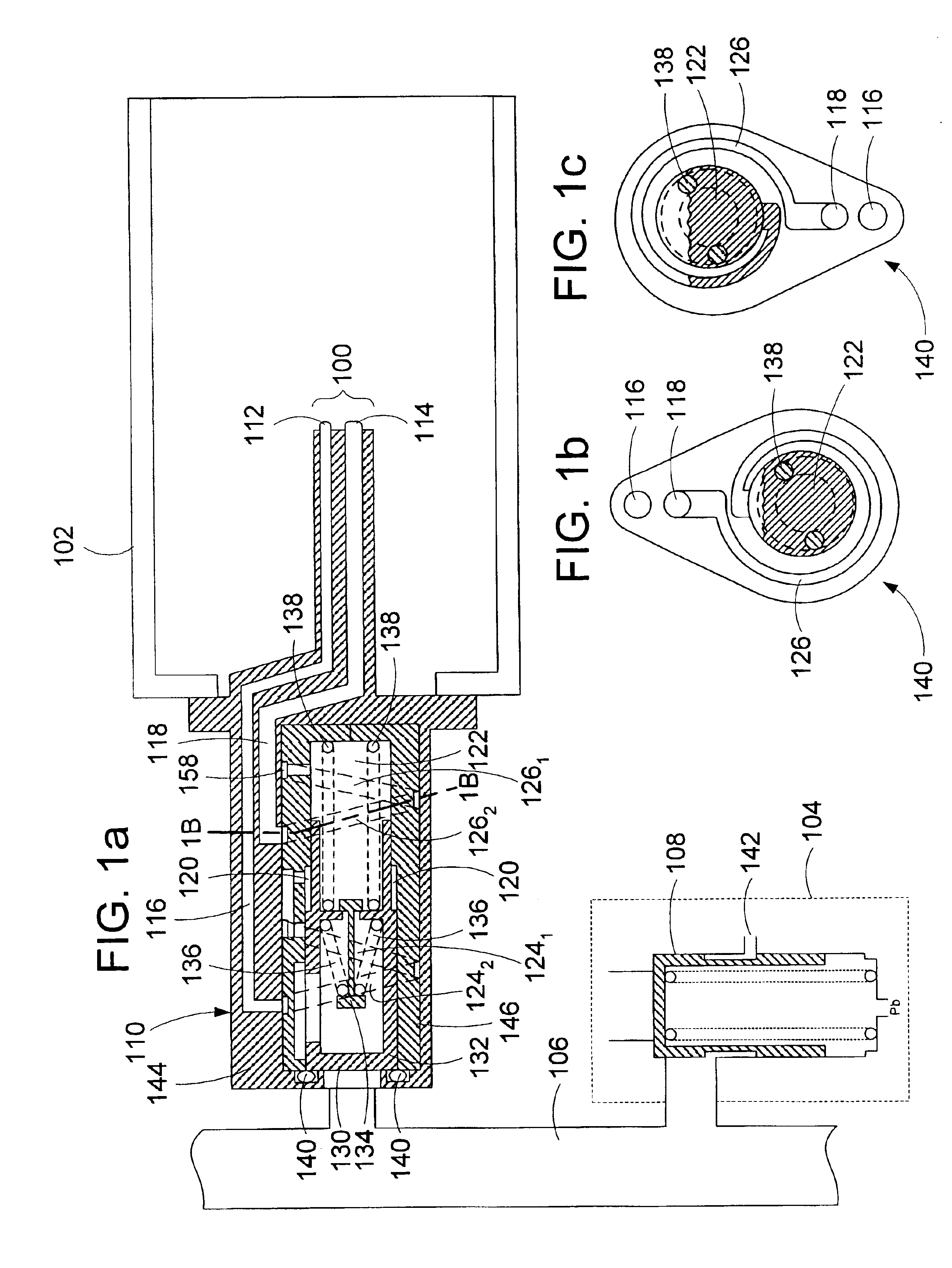
Turning to the drawings, wherein like reference numerals refer to like elements, the invention is illustrated as being implemented in a suitable environment. As illustrated in FIG. 1a, the fuel system described herein generally comprises a plurality of fuel nozzles 100 arranged in a combustion chamber 102, a fuel metering unit 104, and a fuel manifold 106 disposed therebetween. It will be understood by those skilled in the art that the fuel metering unit 104 includes a pressurizing, shutoff, and drain valve 108 which delivers fuel to the fuel nozzles 100 once a predetermined start-up pressure is attained, and a metering valve (not shown) which modulates the fuel flow rate to the fuel nozzles 100 thereafter. It will also be understood that the fuel manifold 106 comprises any means which provides a fluidic connection between the fuel metering unit 104 and the fuel nozzles 100.

Flow is metered by the fuel control and passes into the engine fuel manifold 106 through the fuel control pres...


PUM


Abstract

A fuel system having an ecology valve controlling liquid flow through a retention passage when pressurized liquid is passed through the valve is presented. The retention passage winds between the valve outlet and a cavity such that no matter which way the valve is oriented gravity alone is unable to drain liquid from the cavity to the outlet. The ecology valve serves to suction fuel from fuel nozzle passages upon engine shutdown. Fuel is temporarily stored in the cavity and the retention passage. The ecology valve also provides a fuel splitting function for providing a port geometry determined split between fuel nozzles in the fuel system.

Description

FIELD OF THE INVENTIONThis invention relates generally to fuel delivery systems for engines and more particularly to ecology and fuel flow splitting functions for such fuel delivery systems.BACKGROUND OF THE INVENTIONIn many gas turbine engines, the fuel system for regulating the flow of fuel to the combustion chamber consists of one or more fuel nozzles arranged in the combustion chamber, a fuel pump for pressurizing fuel from the fuel supply, a fuel metering unit for controlling the flow of fuel to the fuel nozzles and one or more fuel manifolds fluidically connecting the fuel metering unit to the fuel nozzles.During engine start-up, fuel is pumped from the fuel supply to the fuel metering unit by the fuel pump and, once a sufficient start-up pressure is attained, the pressurizing valve of the fuel metering unit opens and fuel is supplied to the fuel nozzles via the fuel manifold. Thereafter, the metering valve of the fuel metering unit modulates the rate of fuel flow from the fue...

Claims


Application Information

Patent Timeline
Patent Type & Authority Patents(United States)
IPC IPC(8): F02C7/22F02C7/232
CPCF02C7/232Y02T50/677Y02T50/671F05D2270/08Y10T137/4471Y02T50/60
Inventor WERNBERG, DONALD E.TYSVER, JOHN D.
Owner WOODWARD GOVERNOR CO
Why Eureka
Try Eureka