Ejector cycle

a technology of ejector cycle and nozzle, which is applied in the direction of refrigeration components, transportation and packaging, light and heating apparatus, etc., can solve the problems of difficult to become minute liquid dorps of refrigerant, and the inability to improve the efficiency of nozzle efficiency and ejector efficiency of ejector cycle in a wide load variation area, so as to improve the efficiency of ejector and nozzle efficiency, the effect of wide load variation area

Active Publication Date: 2005-04-12
DENSO CORP
View PDF6 Cites 9 Cited by
  • Summary
  • Abstract
  • Description
  • Claims
  • Application Information

AI Technical Summary

Benefits of technology

In view of the foregoing problems, it is an object of the present invention to provide an ejector cycle having an ejector, which effectively improves an ejector efficiency and a nozzle efficiency in a wide load variation area of the ejector cycle.
It is another object of the present invention to provide an ejector cycle having a variable throttle device upstream of an ejector, which can be effectively operated while preventing a damage of a diaphragm in the variable throttle device.
Because the variable throttle device is provided upstream of the nozzle of the ejector, it is possible to suitably decompress refrigerant before being introduced into the nozzle of the ejector. Accordingly, ejector efficiency and nozzle efficiency can be effectively improved while a sufficient cooling capacity can be obtained in the ejector cycle, in a wide load vibration area of the ejector cycle. In addition, the refrigerant pressure at the refrigerant outlet side of the low-pressure heat exchanger is applied to the side opposite to the back pressure chamber in the variable throttle device, a pressure difference between the back pressure chamber and the side opposite to the back pressure chamber can be made smaller. Generally, the variable throttle device further includes a diaphragm for defining the back pressure chamber, and a valve body displaced in accordance with a movement of the diaphragm to change a throttle open degree. In this case, the pressure introducing means is provided to introduce the refrigerant pressure at the refrigerant outlet side of the low-pressure heat exchanger to the side opposite to the back pressure chamber with respect to the diaphragm. Accordingly, pressure change characteristics of gas sealed in the back pressure chamber can be made suitable, and it can prevent the diaphragm from being damaged due to the pressure difference.

Problems solved by technology

On the other hand, in a center portion separated from the inner wall surface of the nozzle, because refrigerant is difficult to boil, liquid dorps of refrigerant are difficult to become minute.
Therefore, the nozzle efficiency and the ejector efficiency of the ejector cycle cannot be improved in a wide load variation area.

Method used


Image

  • Ejector cycle
  • Ejector cycle
  • Ejector cycle

Examples


first embodiment

(First Embodiment)

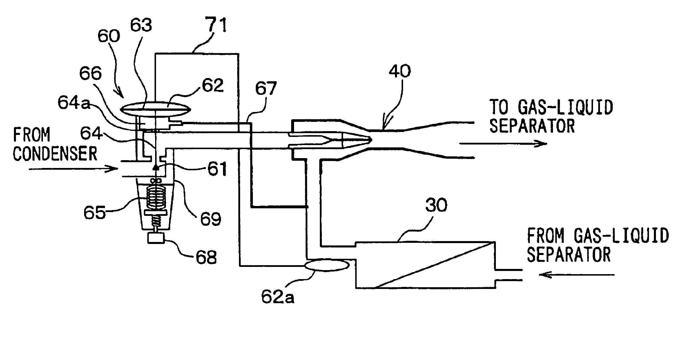
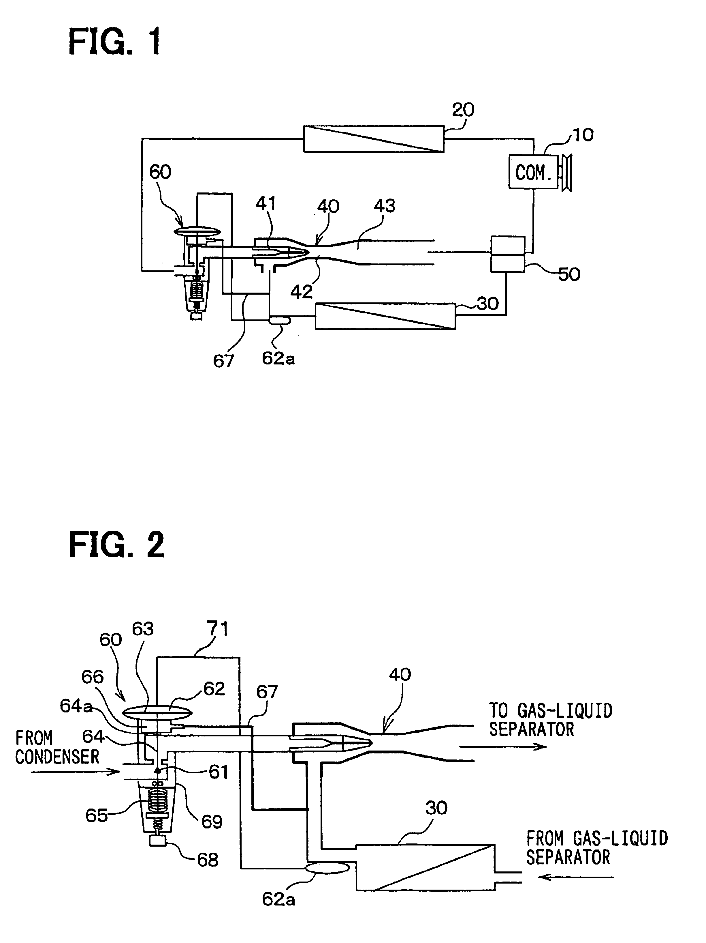
In the first embodiment, an ejector cycle is typically used as a vapor compression refrigerator for a showcase for cooling and refrigerating foods and drinks or as a vapor compression refrigerator mounted in a vehicle for transporting foods and drinks while keeping at a cooling or refrigerating state. As shown in FIG. 1, a compressor 10 is an electric compressor for sucking and compressing refrigerant circulated in the ejector cycle. A condenser 20 (cooler, radiator) is a high-pressure heat exchanger for cooling high-temperature and high-pressure refrigerant discharged from the compressor 10 by performing heat-exchange operation between outside air and the high-temperature and high-pressure refrigerant.

Further, an evaporator 30 is a low-pressure heat exchanger for cooling air to be blown into the showcase by evaporating liquid refrigerant, more specifically, by performing heat-exchange operation between the air and low-pressure refrigerant. An ejector 40 sucks refr...

second embodiment

(Second Embodiment)

The second embodiment of the present invention will be now described with reference to FIG. 4. In the above-described first embodiment, the refrigerant temperature at the refrigerant outlet side of the evaporator 30 is introduced to the back pressure chamber 62 through the temperature sensing portion 62a. However, in the second embodiment, as shown in FIG. 4, a part of the connection rod 64 is exposed in a refrigerant passage through which gas refrigerant sucked from the evaporator 30 flows. That is, as shown in FIG. 4, a part of the connection rod 64 is arranged in a refrigerant passage through which refrigerant from a refrigerant suction port 42a of the ejector 4 flows, so that the refrigerant temperature at the refrigerant outlet side of the evaporator 30 can be sensed by the connection rod 64. At least the part of the connection rod 64, exposed in the refrigerant passage, is made of a high thermal-conductive material such as copper so as to construct a tempera...


PUM


Abstract

In an ejector cycle with an ejector including a nozzle for decompressing refrigerant, a variable throttle device is disposed upstream from the nozzle to decompress and expand high-pressure refrigerant flowing from a condenser. For example, the variable throttle device decompresses the high-pressure refrigerant in a gas-liquid two-phase state at an upstream position from the nozzle of the ejector. In addition, the variable throttle device includes a back pressure chamber having an inner pressure that changes by sensing a refrigerant temperature at a refrigerant outlet side of an evaporator, and a pressure introducing means for introducing a refrigerant pressure of a refrigerant outlet side of the evaporator to a side opposite to the back pressure chamber with respect to a diaphragm. Therefore, a pressure difference between the back pressure chamber and the side opposite to the back pressure chamber can be made smaller.

Description

CROSS-REFERENCE TO RELATED APPLICATIONThis application is related to and claims priority from Japanese Patent Application No. 2003-173844 filed on Jun. 18, 2003, the contents of which are hereby incorporated by reference.BACKGROUND OF THE INVENTION1. Field of the InventionThe present invention relates to an ejector cycle including an ejector. In the ejector cycle, a variable throttle device is disposed upstream of a nozzle of the ejector, so that high-pressure refrigerant is decompressed in the variable throttle device before being decompressed in the nozzle.2. Description of Related ArtIn an ejector cycle, refrigerant is decompressed and expanded in a nozzle of an ejector so that gas refrigerant evaporated in an evaporator is sucked, and pressure of refrigerant to be sucked into a compressor is increased by converting expansion energy to pressure energy. In the nozzle of the ejector, the pressure energy of the refrigerant is converted to the speed energy thereof. Further, because r...

Claims


Application Information

Patent Timeline
Patent Type & Authority Patents(United States)
IPC IPC(8): F25B41/00F25B9/00F25B1/00
CPCF25B41/00B60H2001/3298F25B9/008F25B2309/061F25B2700/21175F25B2341/0012F25B2341/0013F25B2341/0683F25B2600/2513F25B2341/0011
Inventor NISHIJIMA, HARUYUKITAKEUCHI, HIROTSUGUIKEGAMI, MAKOTO
Owner DENSO CORP
Why Eureka
Try Eureka