Device and optical element for the aiming and the visual indication of reading area of a coded information reader

a technology of information reader and optical element, which is applied in the direction of sensing record carrier, sensing electromagnetic radiation, instruments, etc., can solve the problems of unavoidable use of more sources, and increasing the size and cost of the aiming devi

Inactive Publication Date: 2005-04-12
DATALOGIC
View PDF11 Cites 99 Cited by
  • Summary
  • Abstract
  • Description
  • Claims
  • Application Information

AI Technical Summary

Benefits of technology

According to a further variant of the device of the invention, the second face comprises at least one first peripheral surface portion inclined by a predetermined angle α1 with respect to said first face and adapted to deflect said at least one first portion of light beam by a predetermined deflection angle β1 with respect to said optical axis Z, and at least one second central surface portion, inclined by a predetermined angle α2, different from α1, with respect to said first face and adapted to deflect said at least one portion of light beam by a predetermined deflection angle β2, different from β1 with respect to said optical axis Z. In this way, it is advantageously possible to realise, through a single refractive optical element, two different deflection angles; the aiming device is thus capable of identifying two different zones of the reading area, a more internal one (identified by the surface portions having a smaller deflection angle) useful for close-up reading of high-density codes, and a more external one (identified by the surface portions having a larger deflection angle), useful for a distance reading of medium-low density codes.
Advantageously, by increasing the number of inclined faces of the refractive optical element it is possible to increase the number of zones or points identified on the reading area; for example in this way it is advantageously possible to identify, besides the vertices of the framed reading area, also the median points of the outline of said area.

Problems solved by technology

Nevertheless, the use of more sources unavoidably increases the size and cost of the aiming device.
Size and cost increase are often undesirable, particularly in portable optical readers.
A first drawback associated to a device of the type described above relates to the high cost and to the construction difficulty of the holographic and / or diffractive optical elements used.
These drawbacks are essentially due to the difficulty of realizing, on their surface, grooves of minimum sizes.
A second drawback associated with a device of the type described above relates to the fact that, for using a DOE (HOE), it is necessary to have a coherent source (laser source).
As is known, coherent sources are particularly expensive.

Method used


Image

  • Device and optical element for the aiming and the visual indication of reading area of a coded information reader
  • Device and optical element for the aiming and the visual indication of reading area of a coded information reader
  • Device and optical element for the aiming and the visual indication of reading area of a coded information reader

Examples


Embodiment Construction

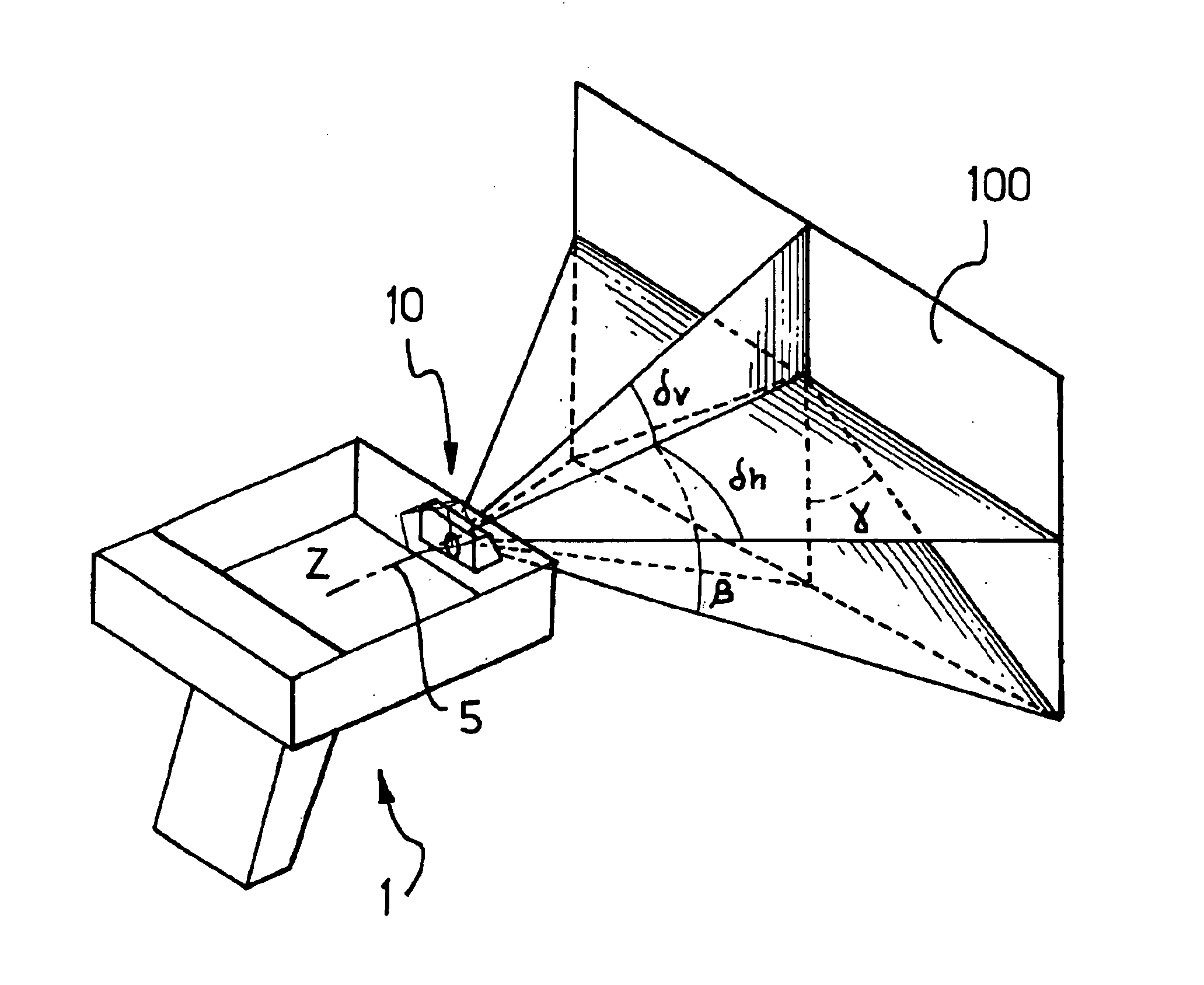
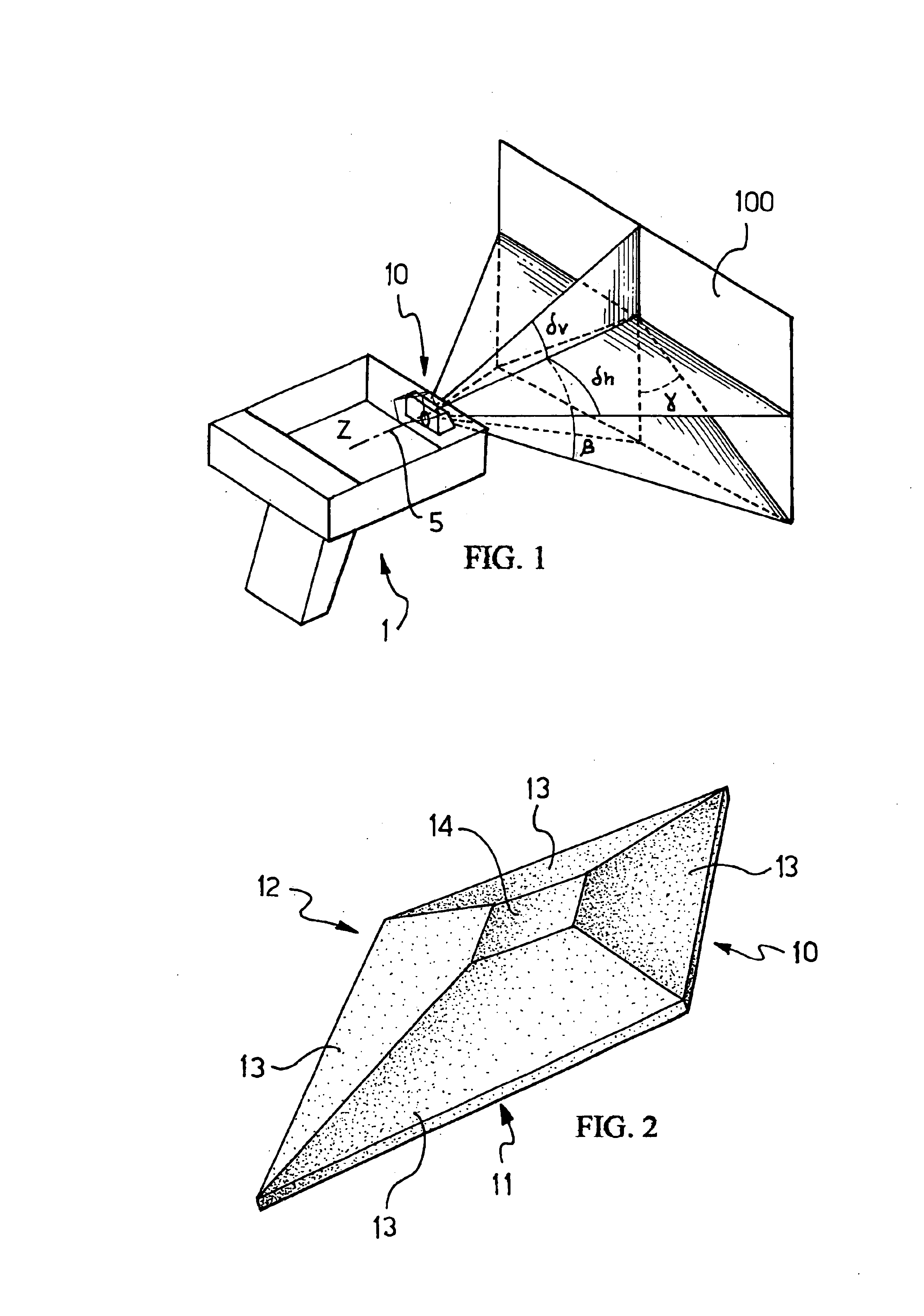
In FIG. 1, reference numeral 1 schematically indicates a coded information reader comprising a device for the aiming and / or the visual indication of a reading area 100 framed by the reader 1, according to the present invention. The reader 1 is preferably a conventional portable coded information reader. Thus, in the present description, reference shall be made to the constructive details of the aiming device of the invention mounted into the reader 1, instead of reader 1 as a whole.

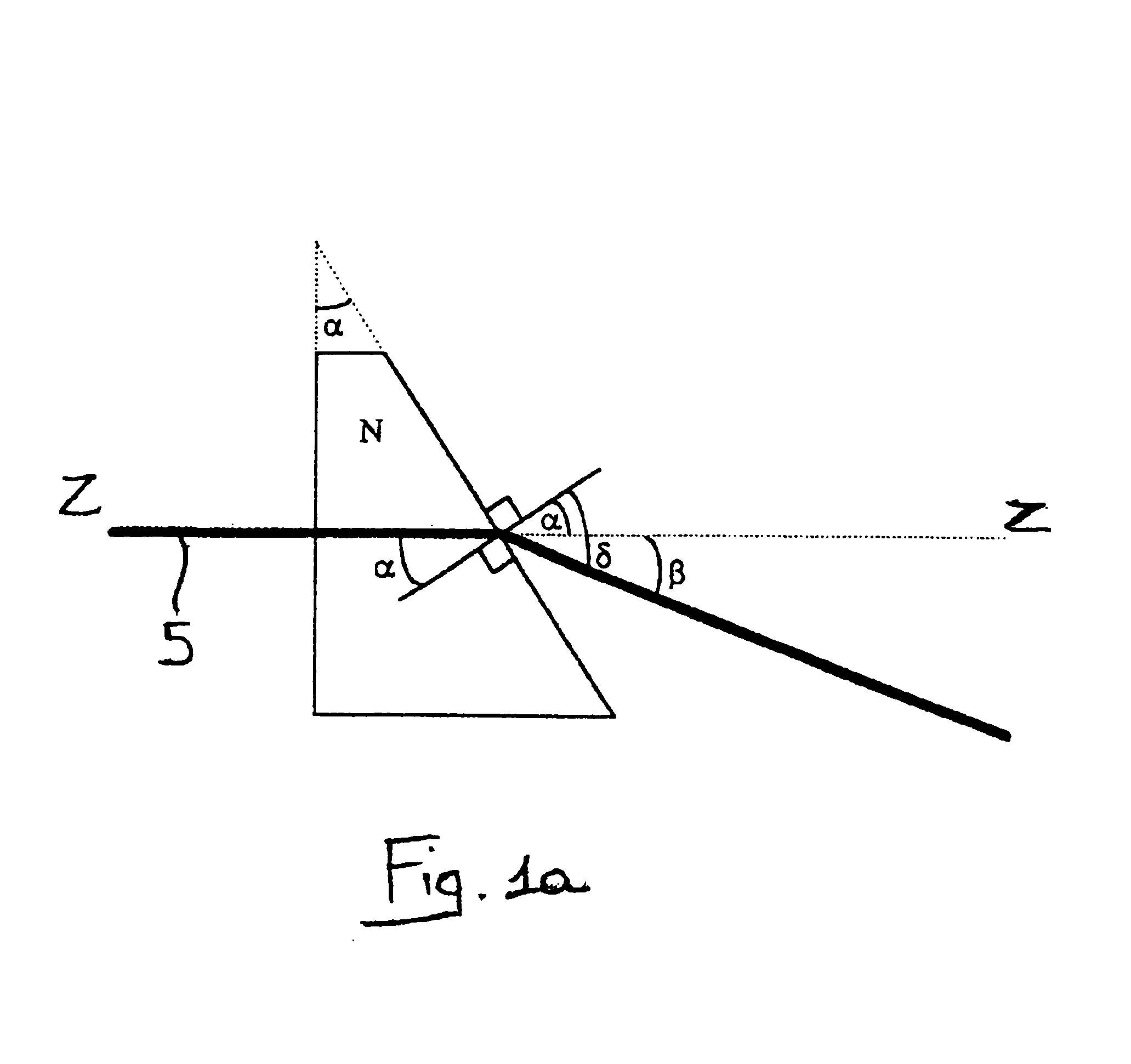
The aiming device of the invention comprises, in particular, an emission source (not illustrated) of a collimated light beam with a substantially circular or elliptical shape (indicated with reference numeral 5). The emission source, which can be of any type (such as for example, a laser source, a LED or a lamp) is preferably followed by a collimation lens (also not illustrated) so that, downstream of the emission source, a collimated light beam 5 is defined. The optical axis intersects the reading area 1...


PUM


Abstract

A device for the aiming and the visual indication of a reading area of a coded information reader includes an emitter which emits a preferably collimated light beam towards a reading area of a coded information reader, as well as a refractive optical element. The refractive optical element deflects at least one first portion of the light beam so as to generate at least two different beam portions active on at least two different zones of the reading area along at least two different optical paths. The refractive optical element includes opposed first and second faces which respectively collect the light beam and project the at least two beam portions onto the reading area. The second face includes at least one (preferably more than one) first surface portion inclined by a predetermined angle α with respect to the first face and adapted to deflect the at least one first light beam portion by a predetermined deflection angle β with respect to the optical axis Z. The device is adapted to be mounted on a coded information reader to provide the operator with a visual indication of the reading area framed by the reader, before carrying out the reading of the information contained in the area.

Description

BACKGROUND1. Field of the InventionThe present invention relates to a device and an optical element for the aiming and the visual indication of a reading area of a coded information reader. More in particular, the invention relates to a device and an optical element for aiming a reading area of a coded information reader (preferably, but not exclusively, a portable reader) for providing the operator with a visual indication of the reading area framed by the reader so as to optimise the subsequent reading operations.The invention also relates to a coded information reader comprising an aiming device of the type described above.2. Related Art and Other ConsiderationsAs known, in recent years coded information readers (for example optical, magnetic and radiofrequency readers) have been proposed on the market, which are capable of localising and decoding the information contained on a support (for example, an optical, magnetic or electronic code associated to an object) placed into a pr...

Claims


Application Information

Patent Timeline
Patent Type & Authority Patents(United States)
IPC IPC(8): G06K7/10
CPCG06K7/10702G06K2207/1011
Inventor OLIVA, GUIDO M.
Owner DATALOGIC
Why Eureka
Try Eureka