
Replaceable ink jet supply with anti-siphon back pressure control

a technology of back pressure control and ink jet cartridge, which is applied in the direction of printing, etc., can solve the problems of waste, failure of printhead, and disposal of ink jet cartridges which are still able to perform adequately, and achieve the effect of cross sectional area

Inactive Publication Date: 2005-04-12
EASTMAN KODAK CO
View PDF20 Cites 16 Cited by
  • Summary
  • Abstract
  • Description
  • Claims
  • Application Information

AI Technical Summary

Benefits of technology

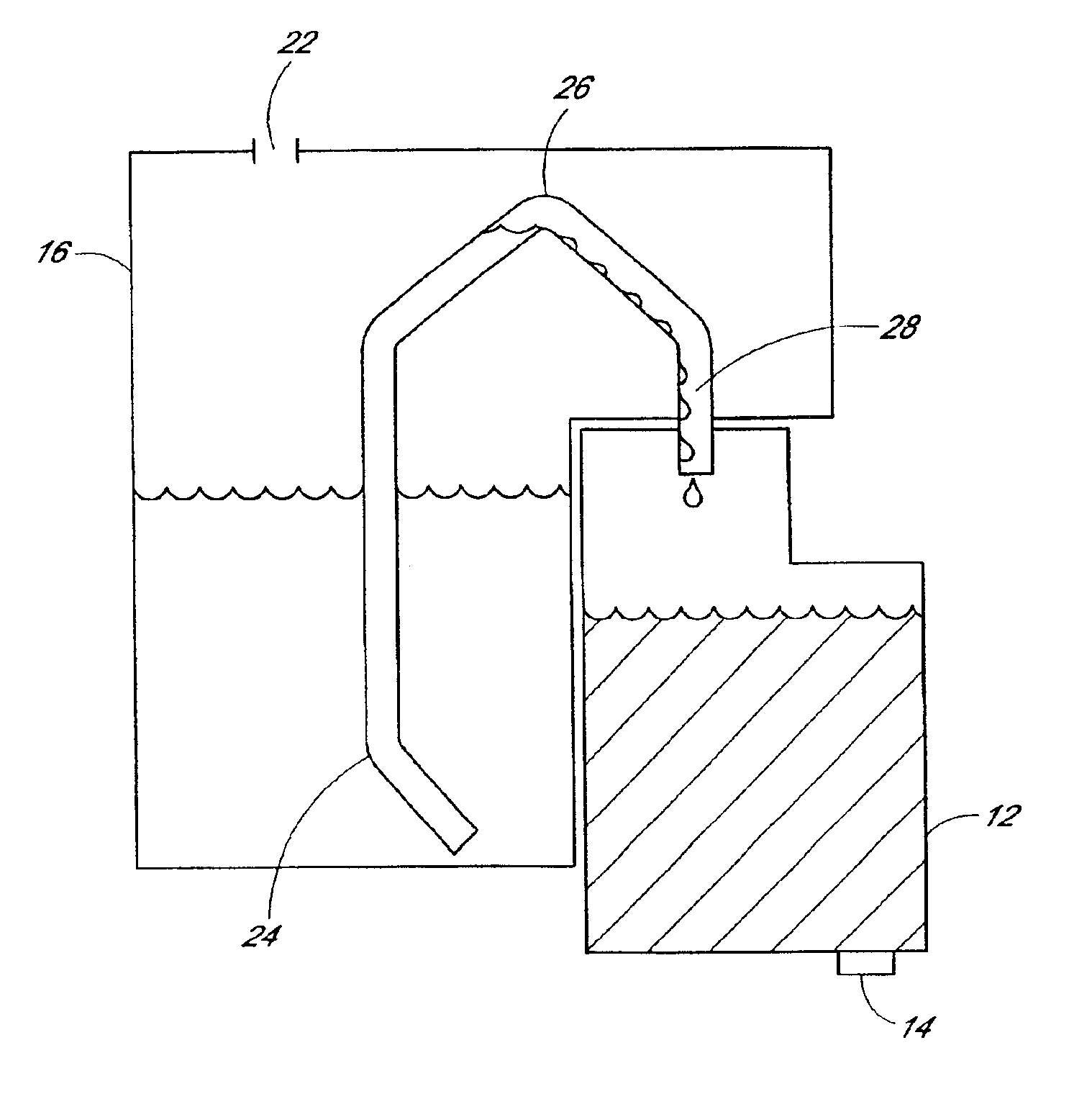
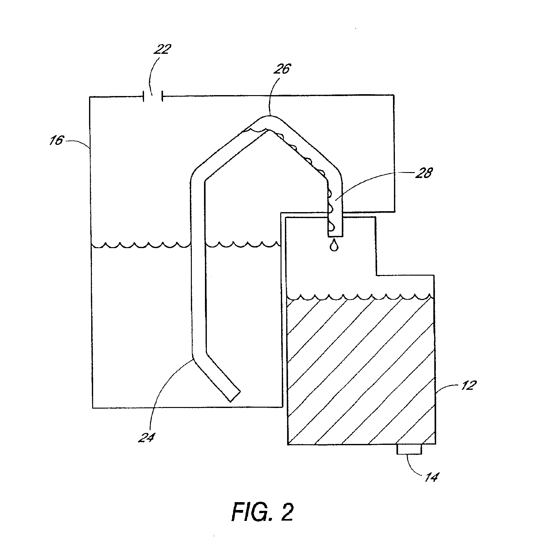
In one embodiment, the invention includes an improved printhead system having an ink supply tank containing a quantity of ink, a pen body having a printhead with a jet plate, and a conduit fluidly connecting the ink supply tank with the pen body. The conduit has a raised portion that carries the ink above a level of ink in the ink supply tank, and the conduit has a siphon break positioned between the raised portion and the jet plate.
In another embodiment, the invention is a printhead system having a pen body housing a first quantity of ink, wherein the pen body has a hollow needle and a printhead with a jet plate. The printhead system has an ink supply tank removably attached to the pen body, wherein the ink supply tank holds a second quantity of liquid ink in a foam-free reservoir, wherein the ink supply tank further has a vent for venting the ink supply tank, wherein the ink supply tank further has a septum configured to be pierced by the hollow needle. The printhead system also has a conduit fluidly connecting the ink supply tank with the pen body for replenishing the first quantity of ink from the second quantity of ink, wherein the conduit carries ink over a raised portion that rises to an elevation higher than a level of the second quantity of ink within the ink supply tank, wherein the conduit further has a siphon break region in a portion of the conduit between the raised portion the jet plate, the siphon break region has a chamber with a cross-sectional area and a height such that ink flow during printer operation does not span the entire cross-section and height of the chamber.
Another embodiment of the invention is a method of supplying ink from an ink supply tank to a printhead through a conduit. The method includes attaching a removable ink supply tank containing a quantity of ink to a pen body comprising a printhead, passing a supply of ink from the ink supply tank through a raised portion of the conduit, wherein the elevation of the raised portion is higher than a lev

Problems solved by technology

Printhead failure is usually due to failure of the resistors used to heat the ink in proximity to each nozzle.
Due to relatively low resistor failure rates, the printhead used in the currently available disposable ink jet cartridges are fully operable to their original print quality specifications after the original ink reservoir has been depleted.
The disposal of these ink jet cartridges which are still able to perform adequately, except for the lack of ink in their supply containers, is wasteful.
However, manually refilling the disposable ink cartridges is often messy and difficult because many disposable ink jet cartridges are not designed with refilling in mind.

Method used


Image

  • Replaceable ink jet supply with anti-siphon back pressure control
  • Replaceable ink jet supply with anti-siphon back pressure control
  • Replaceable ink jet supply with anti-siphon back pressure control

Examples


Embodiment Construction

Embodiments of the invention will now be described with reference to the accompanying figures, wherein like numerals refer to like elements throughout. The terminology used in the description presented herein is intended to be interpreted in its broadest reasonable manner in accordance with its ordinary use in the art and in accordance with any overt definitions provided below.

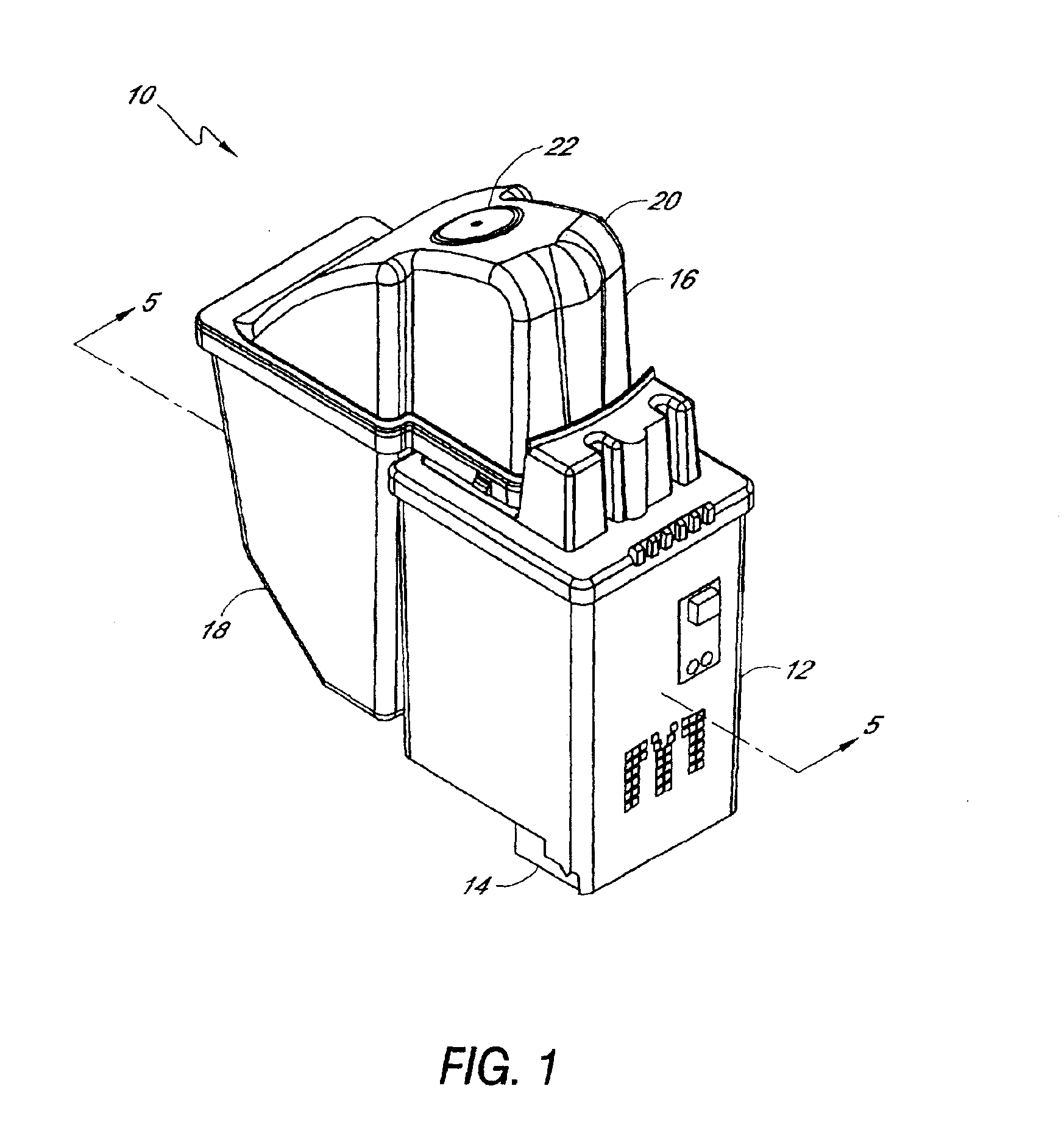
FIG. 1 illustrates a printhead system 10 having a pen body 12 with a printhead 14 mounted thereon. The printhead system 10 can be removably inserted into a print carriage of a typical ink jet printer. Since the mechanisms and electronics within the printer may be conventional, the printer will not be further described in detail. The pen body 12 contains a volume of ink therein in fluid communication with the printhead 14. In one embodiment, the ink is received in a volume of foam contained within the pen body 12 as is known in the art. In FIG. 1, the pen body 12 is shown as mostly rectangular, although it will...


PUM


Abstract

A replaceable ink supply tank that can be mounted to a pen body of a printhead system for use with an ink jet printer. The ink supply tank provides the necessary back pressure for successful operation of the printhead and includes a siphon break in the conduit that supplies ink from the supply tank to the pen body. A conduit connects the ink supply tank to the pen body. The conduit contains a raised portion that is at a level higher than the ink level in the supply tank. The conduit contains a siphon break chamber between the raised portion and the pen body. The conduit further contains an accumulator in the raised portion of the supply tank. The accumulator maintains back pressure in the preferred range to discourage drooling from the nozzle plate during ambient temperature swings.

Description

FIELD OF THE INVENTIONThe present invention relates generally to ink jet printers, and more particularly to an ink jet cartridge with a replaceable ink tank.BACKGROUND OF THE INVENTIONDifferent types of ink jet printers form their droplets of ink employing different methods. There are several technologies used by printer manufacturers, one of the most popular of which is the thermal ink jet. In a thermal ink jet printer, small resistors create heat which vaporizes ink to create a bubble adjacent to a print nozzle. The expansion that creates the bubble causes a droplet of ink to be ejected from the nozzle onto the media. Other technologies include piezo elements to generate pressure waves which cause drop ejection.Ink jet type printers typically employ a printhead cartridge which is moved in a transverse fashion across a print media. Contemporary disposable ink jet printhead cartridges typically include a pen body with a self-contained ink reservoir, a printhead supporting a pluralit...

Claims


Application Information

Patent Timeline
IPC IPC(8): B41J2/175
CPCB41J2/17506B41J2/17523B41J2/17513
Inventor FELLINGHAM, PETER J.PAN, YICHUANBROSCHART, MARK M.ASTROTH, DENNIS J.
Owner EASTMAN KODAK CO
Learn More