Coating device

a coating device and coating technology, applied in the direction of electrostatic spraying apparatus, coating, gasless spraying, etc., can solve the problem of reducing the coating efficiency

Active Publication Date: 2019-03-21
TOYOTA JIDOSHA KK +1
View PDF5 Cites 3 Cited by
  • Summary
  • Abstract
  • Description
  • Claims
  • Application Information

AI Technical Summary

Benefits of technology

[0012]Due to this configuration, the coating material can be restrained from overflowing from the groove portions at the outer edge portion of the rotary head even in the case where the cross-sectional area of the threadlike coating material is maximized.
[0014]Due to this configuration, the coating material can be divided into pieces by the groove portions to the end portion of the rotary head, so the pieces of the discharged threadlike coating material can be restrained from being joined together.

Problems solved by technology

Therefore, there is an inconvenience such as a decrease in coating efficiency.
However, the above-mentioned JP 2017-42749 A does not consider the threadlike coating material discharged from the rotary head, and has room for improvement in this respect.

Method used


Image

  • Coating device
  • Coating device
  • Coating device

Examples


Embodiment Construction

[0028]One of the embodiments of the disclosure will be described hereinafter based on the drawings.

[0029]First of all, a coating device 100 according to the embodiment of the disclosure will be described with reference to FIGS. 1 to 5.

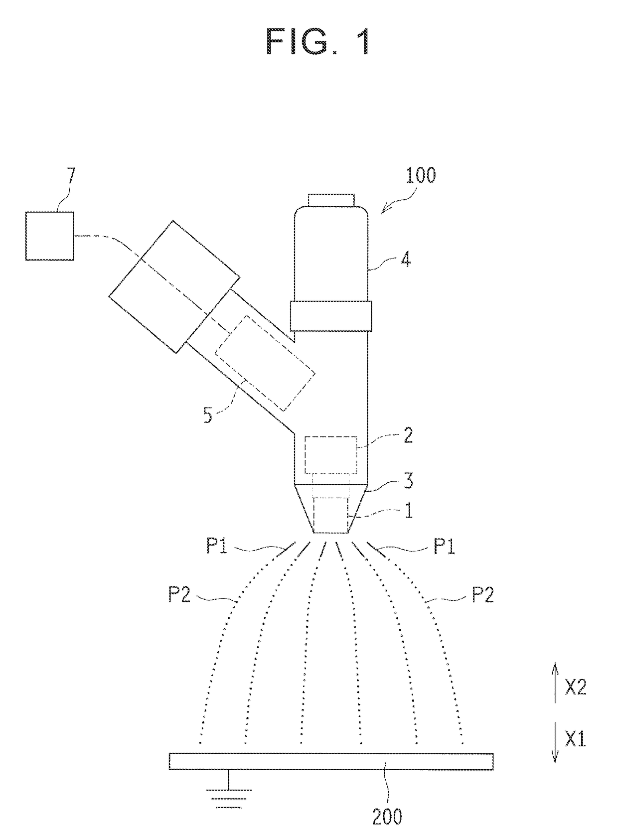
[0030]The coating device 100 is configured to form coating material particles (an atomized coating material) P2 and apply them to an object to be coated 200 by discharging a threadlike coating material P1 from a rotary head 1 and electrostatically atomizing the threadlike coating material P1. Incidentally, the object to be coated 200 is, for example, a body of a vehicle. As shown in FIG. 1, this coating device 100 is equipped with the rotary head 1, an air motor 2, a cap 3, a coating material cartridge 4, and a voltage generator 5.

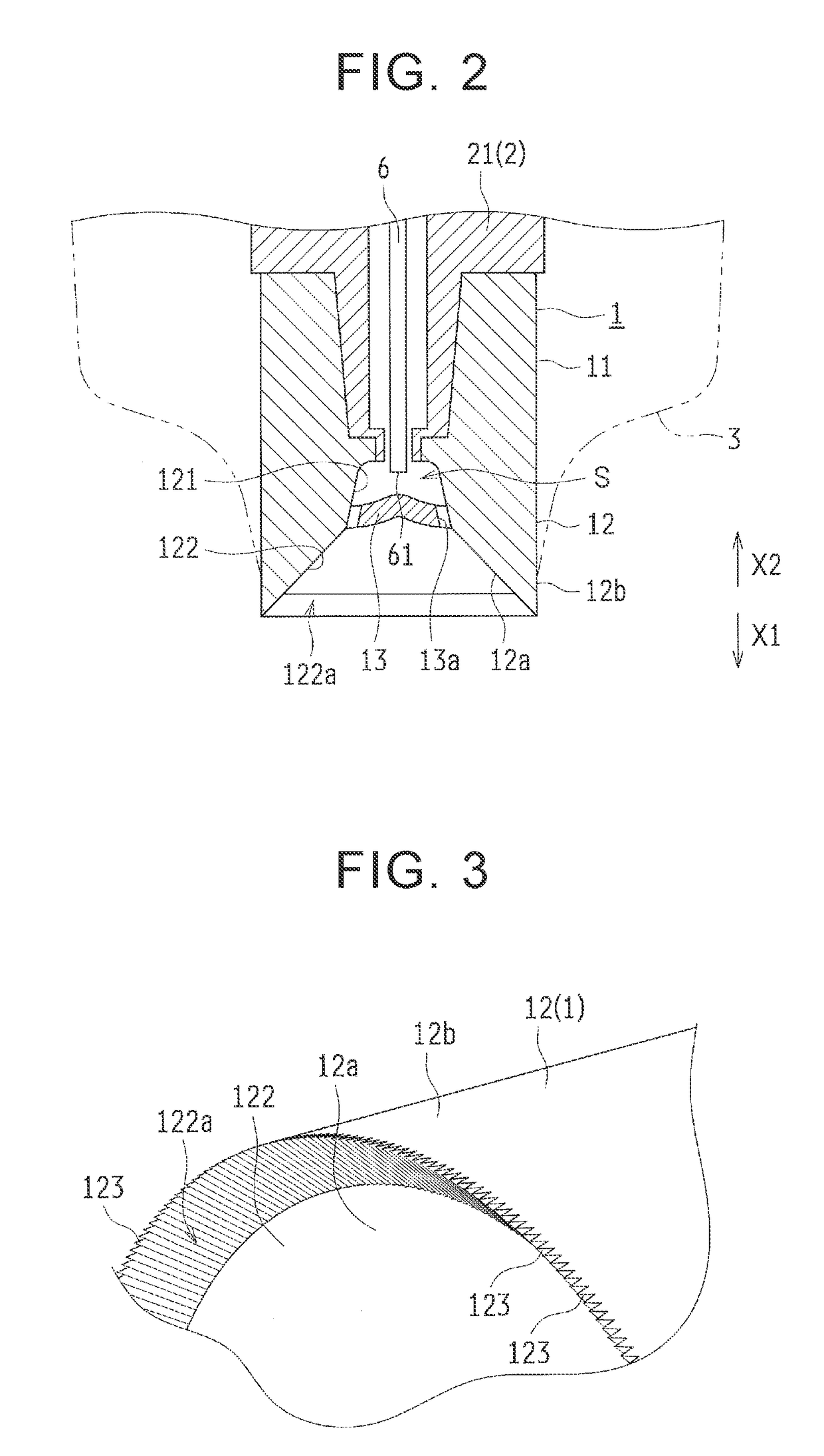
[0031]The rotary head 1 is configured to be supplied with the liquid coating material and discharge the coating material through a centrifugal force. As shown in FIG. 2, this rotary head 1 is cylindrically formed, and include...


PUM


Abstract

A coating device is equipped with a rotary head, a drive unit, and an electric power supply unit. The rotary head is configured to be supplied with a coating material. The rotary head includes a diffusion surface that is configured such that the coating material is diffused toward an outer edge portion of the diffusion surface by a centrifugal force, and a plurality of groove portions that are included in the outer edge portion. The rotary head is configured to discharge a threadlike coating material from the groove portions. Also, the coating device is configured such that a diameter of the threadlike coating material is set equal to or larger than 0.03 mm and equal to or smaller than 0.1 mm and that the threadlike coating material is electrostatically atomized.

Description

INCORPORATION BY REFERENCE[0001]The disclosure of Japanese Patent Application No. 2017-179335 filed on Sep. 19, 2017 including the specification, drawings and abstract is incorporated herein by reference in its entirety.BACKGROUND1. Technical Field[0002]The disclosure relates to a coating device.2. Description of Related Art[0003]Conventionally, there is known a coating device that atomizes (pulverizes) a coating material discharged from a bell cup by blowing shaping air onto the coating material. In this coating device, an accompanying flow of shaping air is reflected by an object to be coated, and coating material particles (the atomized coating material) are kicked up. Therefore, there is an inconvenience such as a decrease in coating efficiency.[0004]Thus, there is proposed a coating device that does not use shaping air (see Japanese Patent Application Publication No. 2017-42749 (JP 2017-42749 A)). The coating device of JP 2017-42749 A is configured to discharge a threadlike coa...

Claims


Application Information

Patent Timeline
Patent Type & Authority Applications(United States)
IPC IPC(8): B05B5/04B05B5/053
CPCB05B5/0403B05B5/053B05B5/035B05B5/0418B05B5/0407B05B5/0411B05B5/04B05B5/006B05C5/02
Inventor TANI, SHINJINUMASATO, AKIRANABESHIMA, ATSUOKONDO, TAKAHITOMURAI, YUKIUENO, TAKAOISHIKAWA, KATSUHIROOKUTA, TAKATOSHIHARADA, KOTA
Owner TOYOTA JIDOSHA KK
Why Eureka
Try Eureka