
Method for Producing a Fuel Cell Stack

a fuel cell and stack technology, applied in the direction of fuel cells, electrochemical generators, electrical equipment, etc., can solve the problem of low material loss, compared to known processes, and achieve the effect of reducing fault susceptibility

Inactive Publication Date: 2008-02-14
STAXERA
View PDF7 Cites 3 Cited by
  • Summary
  • Abstract
  • Description
  • Claims
  • Application Information

AI Technical Summary

Benefits of technology

[0006]The object of the invention is to develop a generic process such that the fault susceptibility is reduced and parallel fabrication becomes possible.
[0007]This object is achieved by arranging a template between a first sealing surface and a second sealing surface, the template having at least one edge area which is located adjacent to the seal section which is to be formed; and placing a sealing compound in the area which is bordered by the first sealing surface, the second sealing surface and the edge area of the template. This approach enables rapid and controlled assembly in which several seals can be aligned at the same time. Furthermore, the material loss, compared to known processes, is low, as is the fault susceptibility. The dimensions of at least one seal section which is to be formed can be easily influenced by the choice of the dimensions of the template.
[0019]In this connection, it is preferred that the first recess of the template is connected to the second recess of the template by way of the first channel. In this case, the second recesses which are aligned with one another can form a filling channel for the sealing compound, the sealing compound traveling by way of the first channel from the fill opening to the first recesses in which preferably the aforementioned mandrel is located. Here, it is considered to be advantageous if the fill channel has a cross sectional area which is relatively large compared to the cross-sectional area of the seal section which is to be formed. In this way, the hydrodynamic pressure loss in the fill channel is much smaller than in the sealing channel when a fluid (or the sealing compound) flows through the two channels.
[0021]Furthermore, it can be provided that the sealing compound present in the second recess in the first duplicating unit and / or in the second recess in the second duplicating unit and / or in the second recess in the template is at least partially removed again, especially using a second mandrel. Alternatively, the sealing compound can remain in the channel formed by the second recesses and can cure there in order to increase the stability of the overall structure.

Problems solved by technology

Furthermore, the material loss, compared to known processes, is low, as is the fault susceptibility.

Method used


Image

  • Method for Producing a Fuel Cell Stack
  • Method for Producing a Fuel Cell Stack
  • Method for Producing a Fuel Cell Stack

Examples


Embodiment Construction

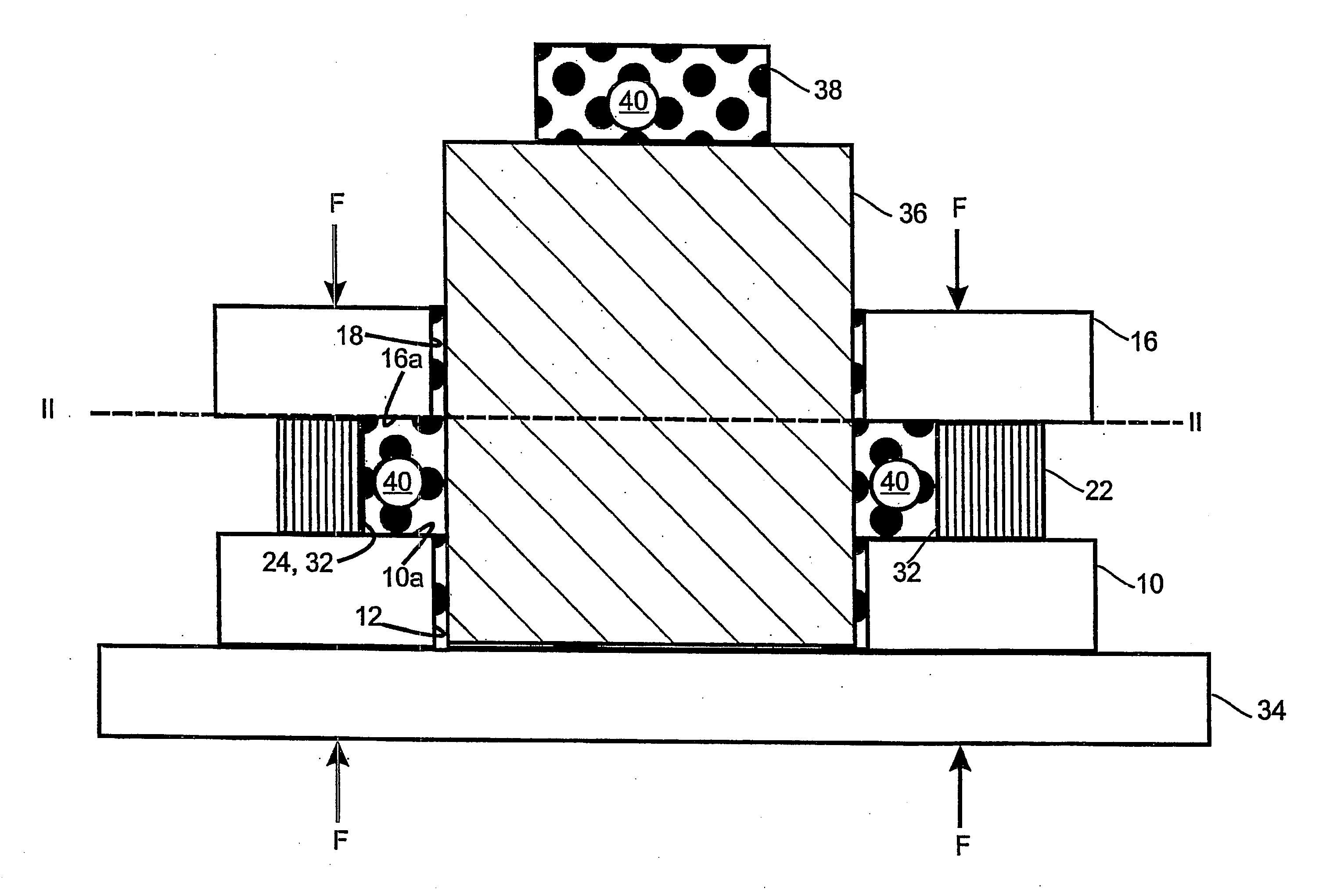
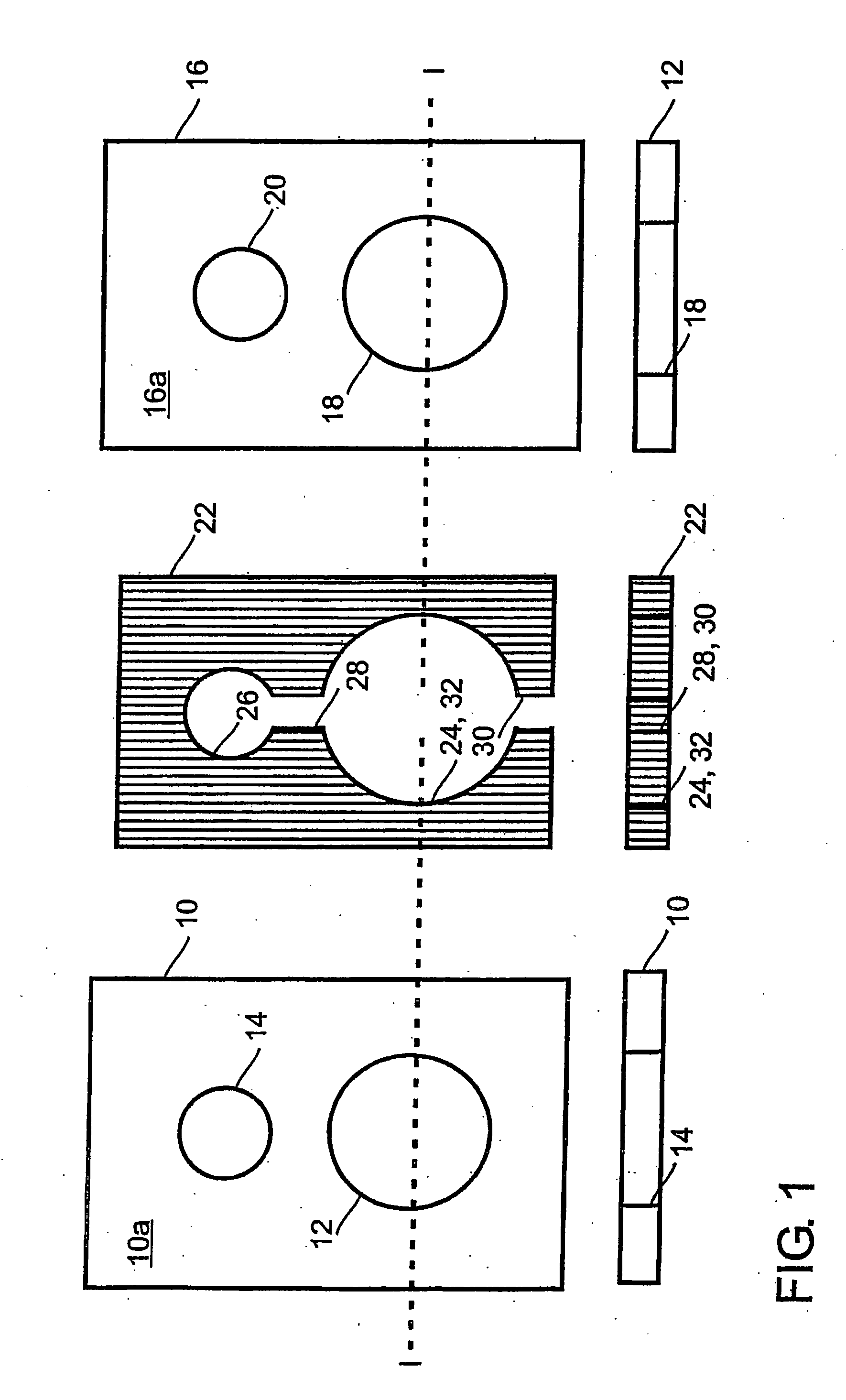
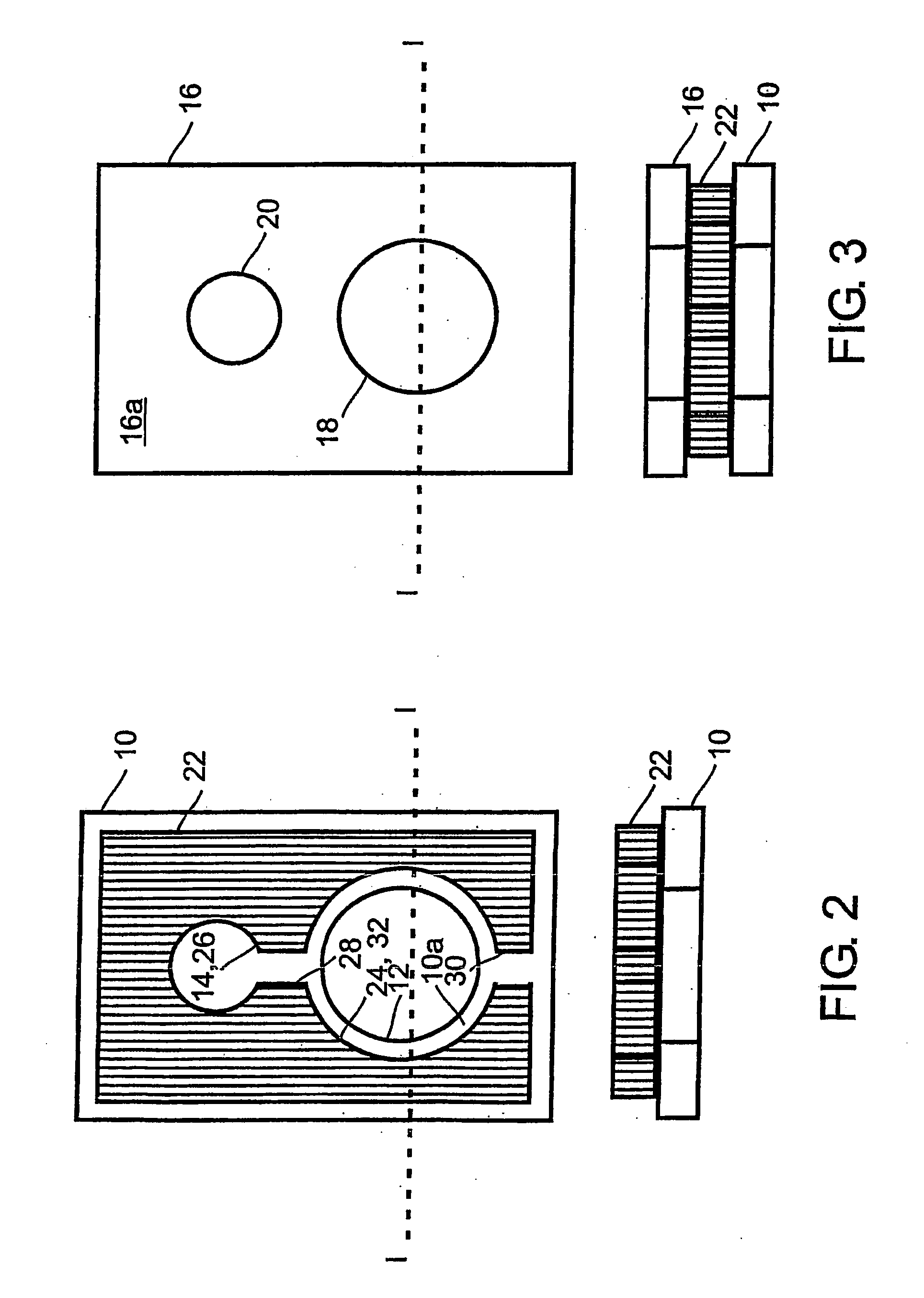
[0032]FIG. 1 shows a first duplicating unit 10, a second duplicating unit 16 and a template 22. As shown in FIG. 1, the first duplicating unit 10 has a first sealing surface 10a and a first opening 12 and a second opening 14. The second duplicating unit 16 has a second sealing surface 16a and a first recess 18 and a second recess 20.

[0033]In this case, the structure of the first duplicating unit 10 and the structure of the second duplicating unit 16 are identical, although the invention is not limited to these embodiments since applications are also possible in which seals arranged differently are formed between different duplicating units.

[0034]A template 22 is shown between the first duplicating unit 10 and the second duplicating unit 16. The template 22 has a first recess 24 and a second recess 26. The periphery of the first recess 24 in the template 22, in this case, defines an edge area 32 which is intended to be located adjacent to the seal section which is to be formed. The f...


PUM

PropertyMeasurementUnit
areaaaaaaaaaaa
edge areaaaaaaaaaaa
dimensionsaaaaaaaaaa

Abstract

A method for producing a fuel cell stack having the following steps: a) providing a first duplicating unit (10) with a first sealing surface (10a) and at least one second duplicating unit (16) with a second sealing surface (16a) and b) forming at least one sealing section (42) between the first sealing surface (10a) and the second sealing surface (16a). The step b) includes the steps of: b1) arranging a template (22) between the first sealing surface (10a) and the second sealing surface (16a), whereby the template (22) has at least one edge area (32) which is arranged adjacent to the sealing section to be formed (42), and b2) introducing a sealing compound (40) into an area which is defined by the first sealing surface (10a), the second sealing surface (16a) and the edge area (32) of the template (22).

Description

BACKGROUND OF THE INVENTION[0001]1. Field of the Invention[0002]The invention relates to a process for producing a fuel cell or a fuel cell stack with the following steps: a) Providing a first duplicating unit with a first sealing surface, and at least a second duplicating unit with a second sealing surface; and b) forming at least one seal section between the first sealing surface and the second sealing surface.[0003]2. Description of Related Art[0004]For example, SOFC fuel cell stacks (SOFC=“solid oxide fuel cell”) comprise a plurality of so-called duplicating units between which there are seals which, in many cases, establish the spacing of the duplicating units, and for example, seal openings which extend in the stack direction of the fuel cell stack. Furthermore, there are generally an upper and a lower end plate and current collector plates. Fuel cell stacks are known in which the individual layers are rigidly cemented (for example, by a glass paste), as are fuel cell stacks w...

Claims


Application Information

Patent Timeline
Patent Type & Authority Applications(United States)
IPC IPC(8): H01M8/24H01M8/02
CPCH01M8/0273Y10T29/4911Y02E60/50H01M8/242H01M8/2425
Inventor STELTER, MICHAEL
Owner STAXERA
Learn More