Fluid rotary machine with a sensor arrangement

a technology of sensor arrangement and rotary machine, which is applied in the direction of rotary or oscillating piston engines, rotary piston engines, instruments, etc., can solve the problems of inability to ensure tightness and extreme torque required to rotate the transmitter, and achieve the effect of simplifying manufacturing

Active Publication Date: 2014-11-25
WHITE DRIVE MOTORS & STEERING SP Z O O
View PDF22 Cites 0 Cited by
  • Summary
  • Abstract
  • Description
  • Claims
  • Application Information

AI Technical Summary

Benefits of technology

[0012]In this embodiment, it is utilised in an advantageous manner that the accommodation seals the inside of the machine towards the outside, so that no opening is required at the sensor arrangement, through which a moving element is guided and which must then be sealed. If a sealing between moving parts can be saved, this improves the operation safety. The wear remains small and the fault susceptibility is reduced. If, for example, the sensor arrangement is connected to a hydraulic machine, hydraulic fluid can enter the accommodation area, thus lubricating at the same time the contact faces between the transmitter and the housing or another element. This again causes that the transmitter can rotate practically freely, so that an extremely small torque is required to rotate the transmitter. When using a transfer element, this again keeps the distortion of the transfer element small. A particularly simple embodiment provides arrangement of the accommodation area inside the housing. The accommodation area can be formed as an accommodation chamber.
[0015]Preferably, the sensor arrangement comprises a sensor housing, in which the accommodation area is arranged. In this embodiment, the sensor housing is sealing the inside of the machine towards the outside. Also in this case the sensor arrangement requires no opening for a movable element, which opening would have to be sealed. The sensor housing can be made as a separate component. Firstly, this simplifies the manufacturing. Secondly, this makes it easy to adapt the sensor housing particularly well to the requirements of the sensor arrangement, particularly those of the transmitter.
[0018]Preferably, the receiver is clamped onto the sensor housing. Thus, the receiver is connected to the sensor housing by means of a detachable connection that can be made and detached again relatively quickly. This has the advantage that by replacing the receiver, the machine can relatively easily be provided with different kinds of sensor arrangements. Also repair work is simplified. In a sensor arrangement the receiver is usually the most fault-susceptible part.
[0022]Preferably, the sensor arrangement comprises an output element that supplies a rectangle signal. However, the output element can also supply an analogue current signal, which particularly varies between 2 milliampere and 20 milliampere. Alternatively, an analogue voltage signal can be supplied, which typically varies between 0.1 Volt and 0.9 Volt. However, a rectangle signal has the advantage of being less noise sensitive. For example, a TTL signal can be chosen as rectangle signal.

Problems solved by technology

This again causes that the transmitter can rotate practically freely, so that an extremely small torque is required to rotate the transmitter.
Otherwise, the tightness would no longer be guaranteed.

Method used


Image

  • Fluid rotary machine with a sensor arrangement
  • Fluid rotary machine with a sensor arrangement
  • Fluid rotary machine with a sensor arrangement

Examples


Embodiment Construction

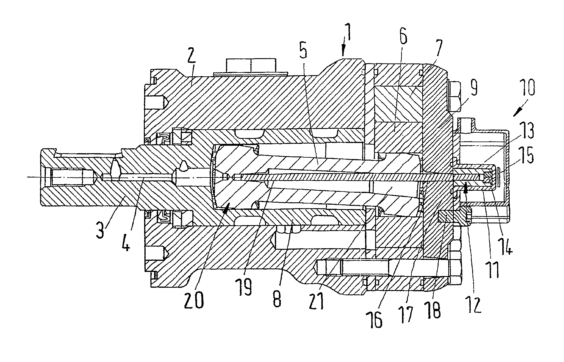
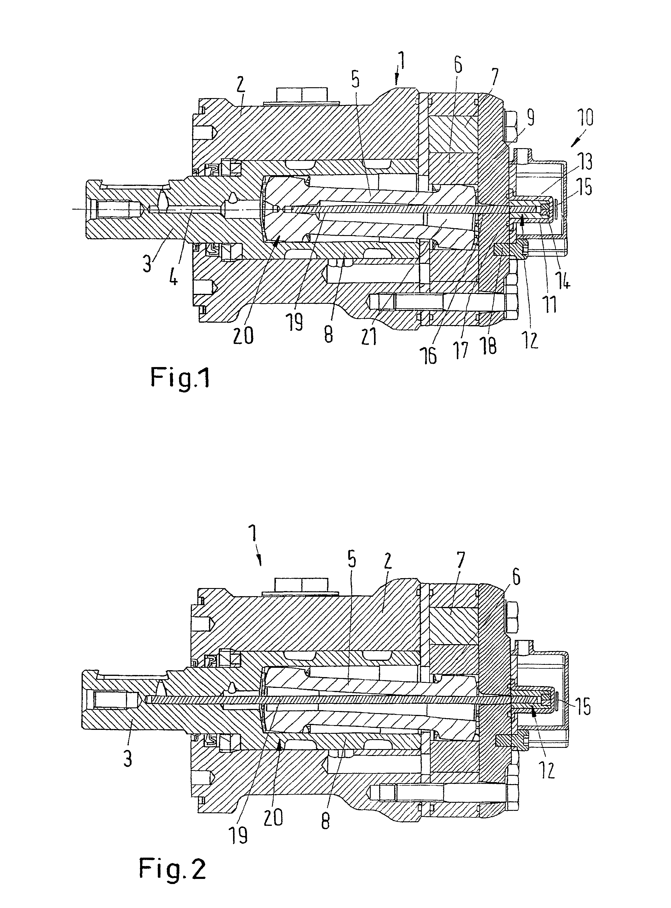
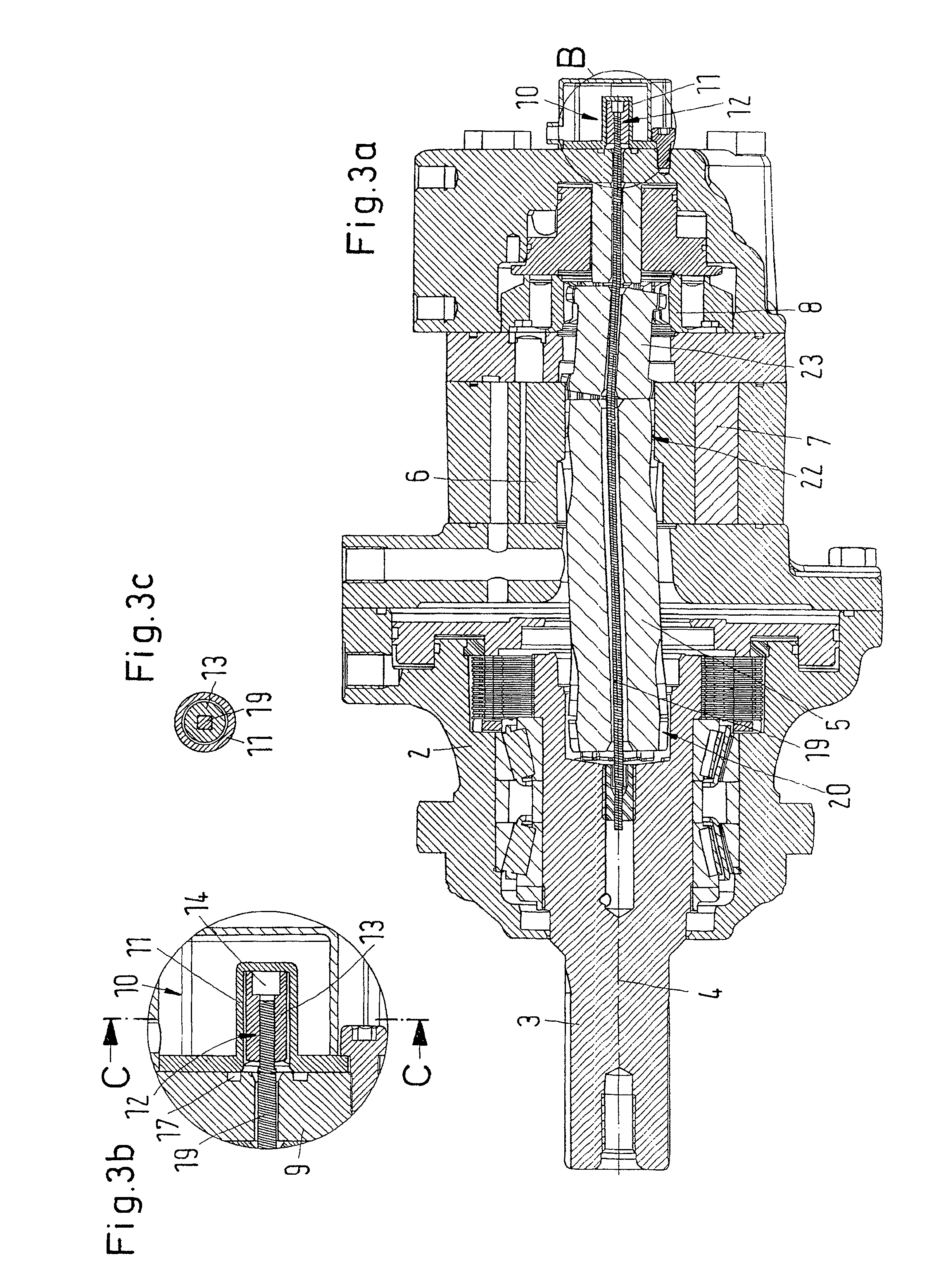
[0031]In the following, the invention is described on the basis of a hydraulic motor as an example of a fluid rotary machine. However, the invention is not limited to hydraulic motors.

[0032]A hydraulic motor 1 as shown in FIG. 1 comprises a housing 2, from which a shaft 3 is led out. A mechanical output can be taken from the shaft 3.

[0033]The shaft 3 is rotatable around an axis 4. The shaft 3 forms part of a movement chain that also comprises a cardan shaft 5 and an externally toothed gear wheel 6 that is arranged in an internally toothed ring 7 to form pressure pockets as known per se, which can, in dependence of their position, be supplied with hydraulic fluid under pressure or release hydraulic fluid to a low-pressure connection. For the control of the fluid supply to these pressure pockets a schematically shown control slide 8 is provided that is connected to the shaft 3.

[0034]Thus, with the gear wheel 6, the movement chain has a first section that orbits around the axis 4. Furt...


PUM


Abstract

The invention concerns a fluid rotary machine (1) with a housing (2), a shaft (3) led out of the housing (2) and a sensor arrangement (10) comprising a transmitter (12) in active connection with the shaft (3), and a receiver (15). It is endeavored to arrange the sensor arrangement in an advantageous manner on the fluid rotary machine. For this purpose, the sensor arrangement (10) comprises an accommodation area, in which the transmitter (12) is arranged, the accommodation area being in fluid connection with the inside of the housing (2) and sealed towards the outside, and the receiver (15) is arranged outside the housing (2) and the accommodation area.

Description

CROSS REFERENCE TO RELATED APPLICATIONS[0001]Applicant hereby claims foreign priority benefits under U.S.C. §119 from German Patent Application No. 10 2010 012 850.3 filed on Mar. 25, 2010, the contents of which are incorporated by reference herein.TECHNICAL FIELD[0002]The invention concerns a fluid rotary machine with a housing, a shaft led out of the housing and a sensor arrangement comprising a transmitter in active connection with the shaft, and a receiver.BACKGROUND OF THE INVENTION[0003]Such a machine is known from U.S. Pat. No. 6,539,710 B2. The first section comprises an externally toothed gear wheel that interacts with an internally toothed ring. Pressure pockets are formed between the gear wheel and the ring, said pressure pockets being either provided with pressure fluid or connected to a low-pressure area via a rotary valve slide arrangement. The gear wheel is connected to the shaft via a cardan shaft. The gear wheel engages a crank pin that transfers the orbiting moveme...

Claims


Application Information

Patent Timeline
Patent Type & Authority Patents(United States)
IPC IPC(8): F03C2/08G01D21/00
CPCF04C2240/81F04C2270/052F03C2/08F04C2270/86F04C2/104
Inventor TYCHSEN, TOMWEISS, DIETMAR
Owner WHITE DRIVE MOTORS & STEERING SP Z O O
Why Eureka
Try Eureka