Automatic tool change device

A technology for automatic tool and tool replacement, applied in the direction of feeding device, manufacturing tool, positioning device, etc., can solve the problem of impossible to rotate the holding device and so on

Inactive Publication Date: 2009-07-15
MASCHFAB MULLER WEINGARTEN AG
View PDF9 Cites 0 Cited by
  • Summary
  • Abstract
  • Description
  • Claims
  • Application Information

AI Technical Summary

Problems solved by technology

It is therefore not possible to turn the holding device due to space constraints

Method used


Image

  • Automatic tool change device
  • Automatic tool change device
  • Automatic tool change device

Examples


Embodiment Construction

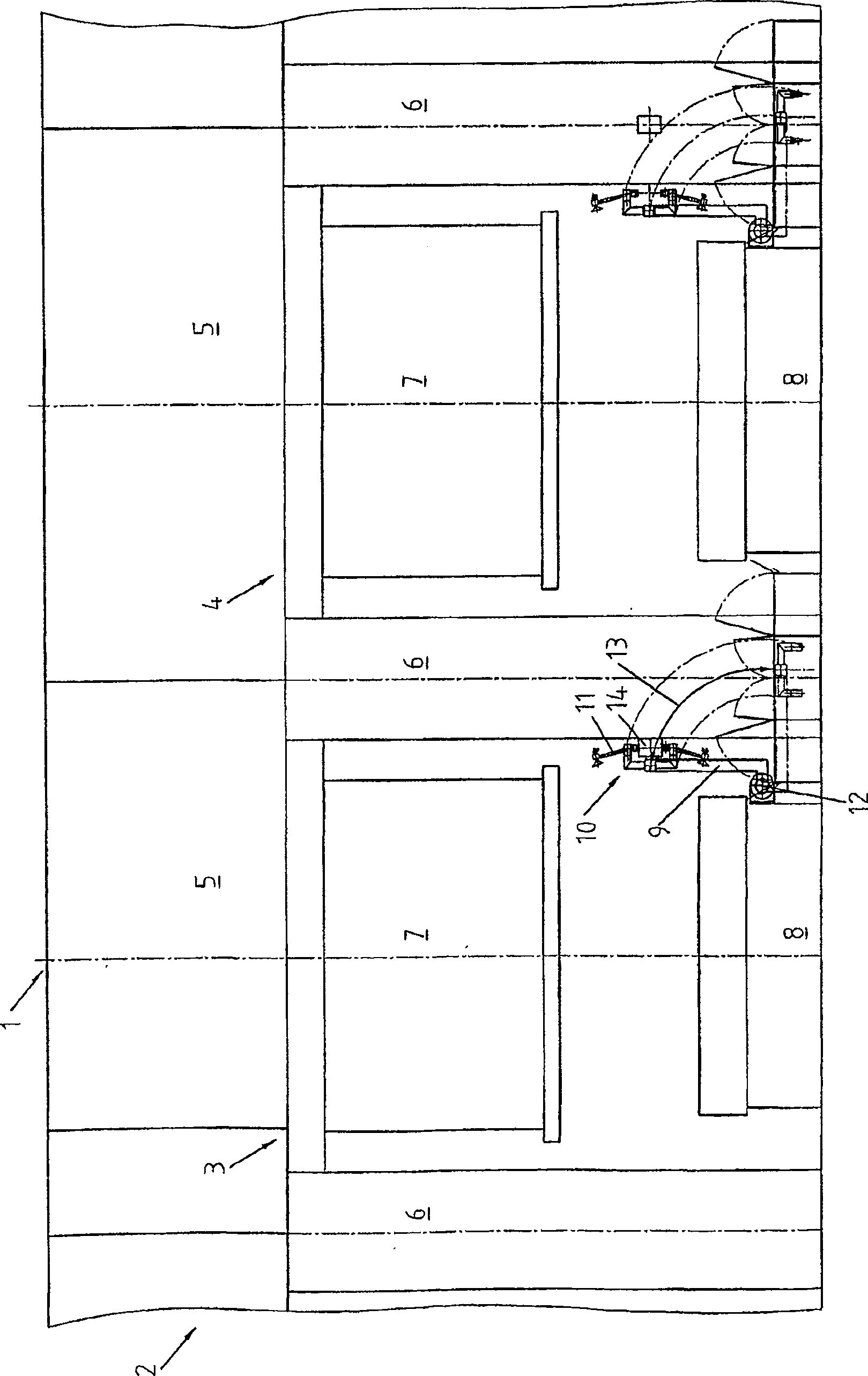
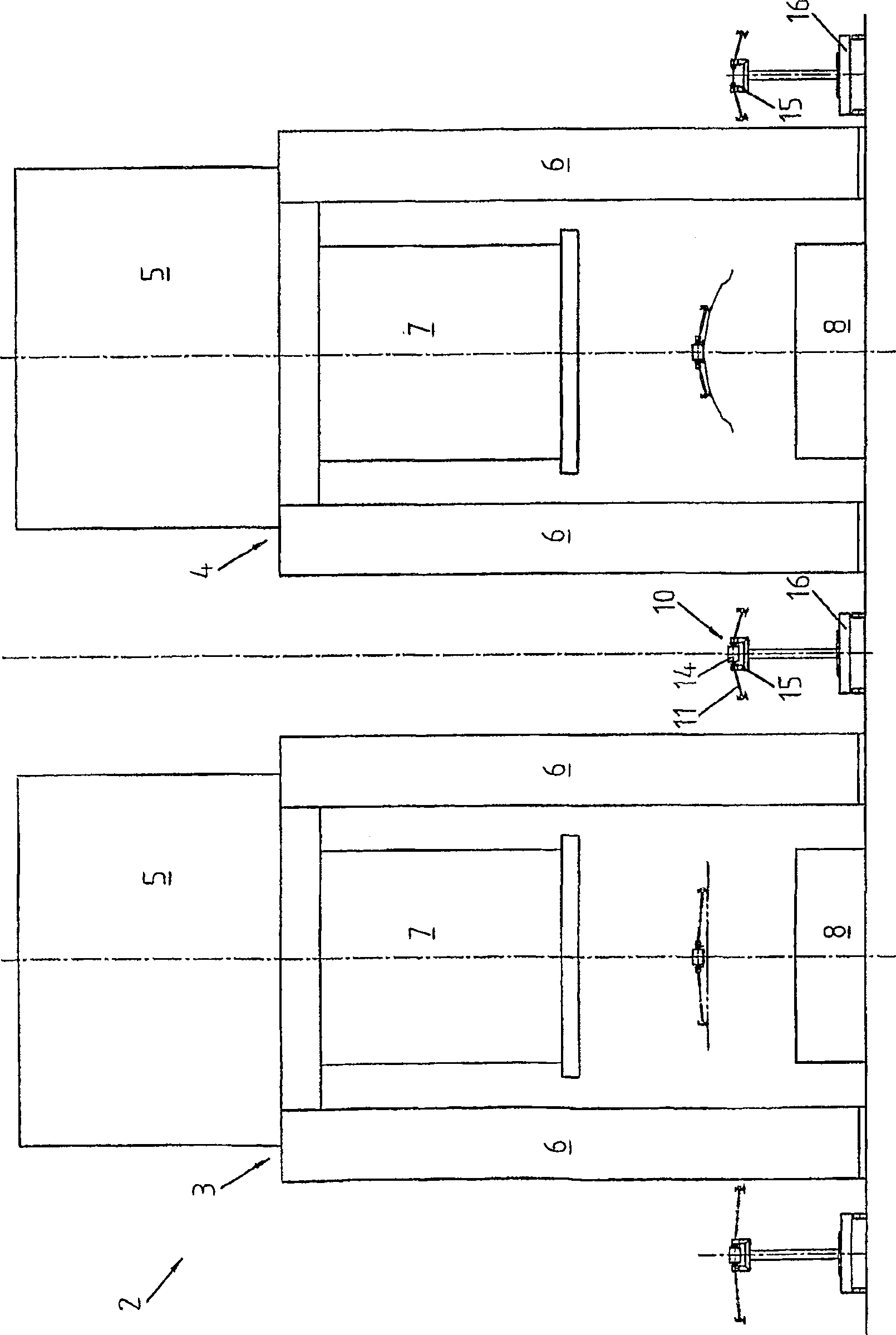
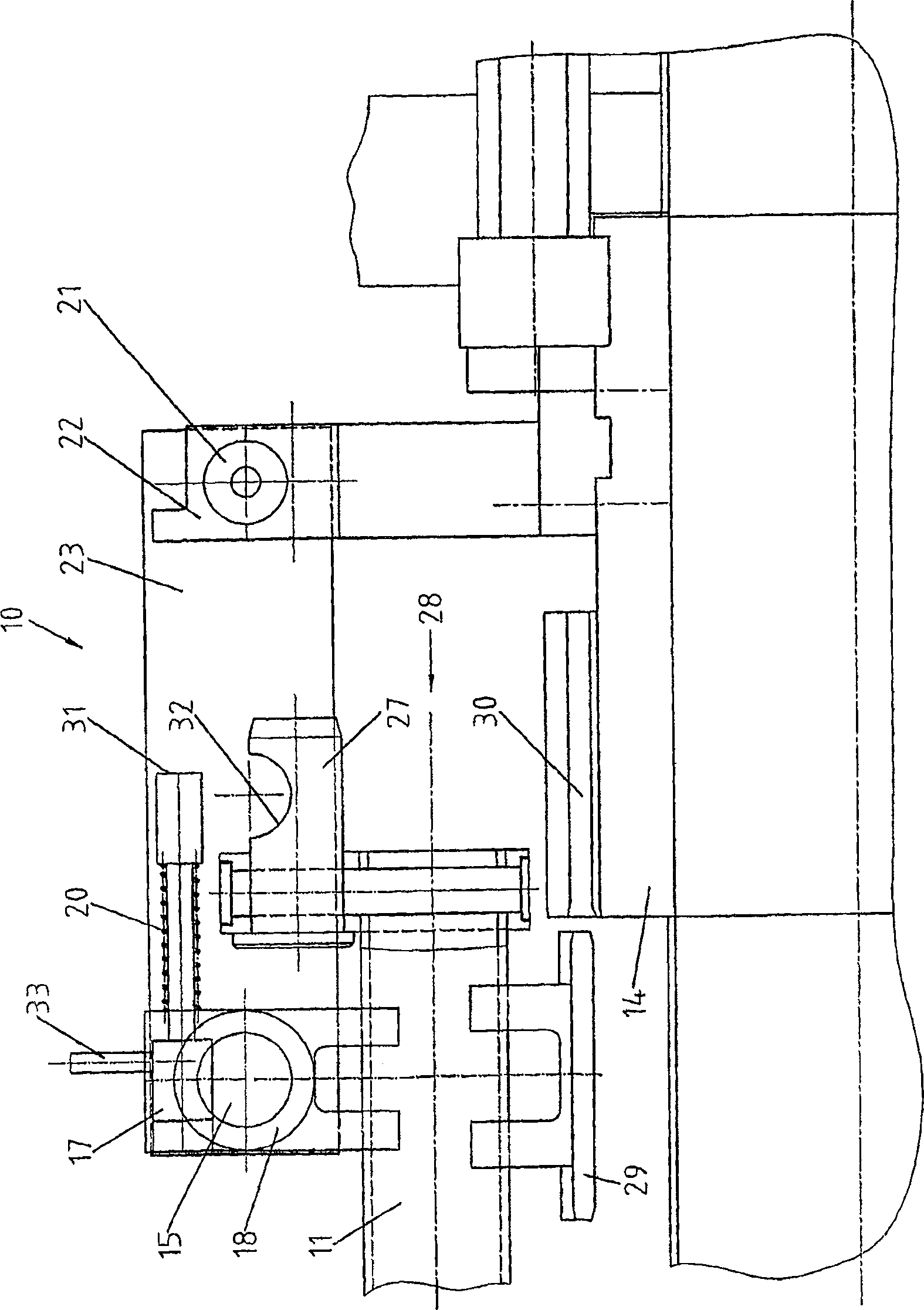
[0040] figure 1 A simplified diagram of a part of a large part transfer press 1 is shown. The figures show machining stages 3 and 4 with head piece 5 , column 6 and slide 7 . Since the tool changing system as claimed in the invention is independent of the type of parts transfer system, the latter is not shown in detail. Only the automatic tool changing system 10 is shown with the beam 14 mounted thereon. A rotary device 9 for holding the automatic tool changer 10 and the tool 11 is mounted on the slide table 8 . In this embodiment, in the event of a tool change, the tool 11 locked on the rotary device 9 is moved out of the large part transfer press 1 together with the slide table 8 and the changed tool is subsequently moved into the large part transfer press 1 . The swivel device 9 serves as a holding device for the tool 11 and is mounted on the slide table 8 so that it can be swiveled at a swivel point 12 . In the case of a tool change, as soon as the tool 11 is detached ...


PUM


Abstract

The invention relates to an automatic tool changer (10) for use in a forming press (1). The unit includes an automatic parts transfer system that allows quick and fully automated tool changes.

Description

technical field [0001] The invention relates to an automatic tool changing device for a forming press with an automatic part transfer system for fast and complete automatic tool changing. Background technique [0002] Production of workpieces that require multiple process operations such as die forging or cutting, usually in so-called multiple slide transfer presses or press lines. The number of tools corresponds to the number of steps required for production. There is a transfer device between each step to transfer the workpiece from one processing position to the next processing position. In conventional designs of these conveyors, grippers or transport rails extending the entire length of the press are moved by cam-controlled drives. On these rails there are grippers or holding elements which hold the workpieces during their transport. [0003] On the one hand, this type of design is characterized by its own high operational reliability; on the other hand, however, it ...

Claims


Application Information

Patent Timeline
Patent Type & Authority Patents(China)
IPC IPC(8): B21D43/05
CPCB21D43/057B21D43/18
Inventor R·雷申巴克
Owner MASCHFAB MULLER WEINGARTEN AG
Why Eureka
Try Eureka